


User Manual: BlueBoard-LPC214X
Revision 1.3
10
3.2.1 LEDs and SPI0
Test setup:
Connect jumpers to all pins of J9 to enable the LED's.
A few seconds after the Blueboard is turned ON or reset; the LEDs will turn ON in ascending pattern and will
turn OFF in descending order and this pattern will repeat three times. Please note that all the LEDs should glow; this
confirms the working of LEDs. Now, since the LEDs are connected through a serial to parallel converter this test also
confirms the working of SPI0 of the LPC.
3.2.1
UART0 & UART1
Test setup:
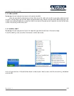
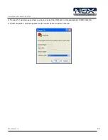
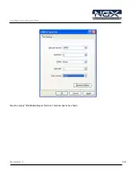
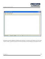
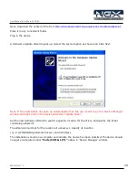
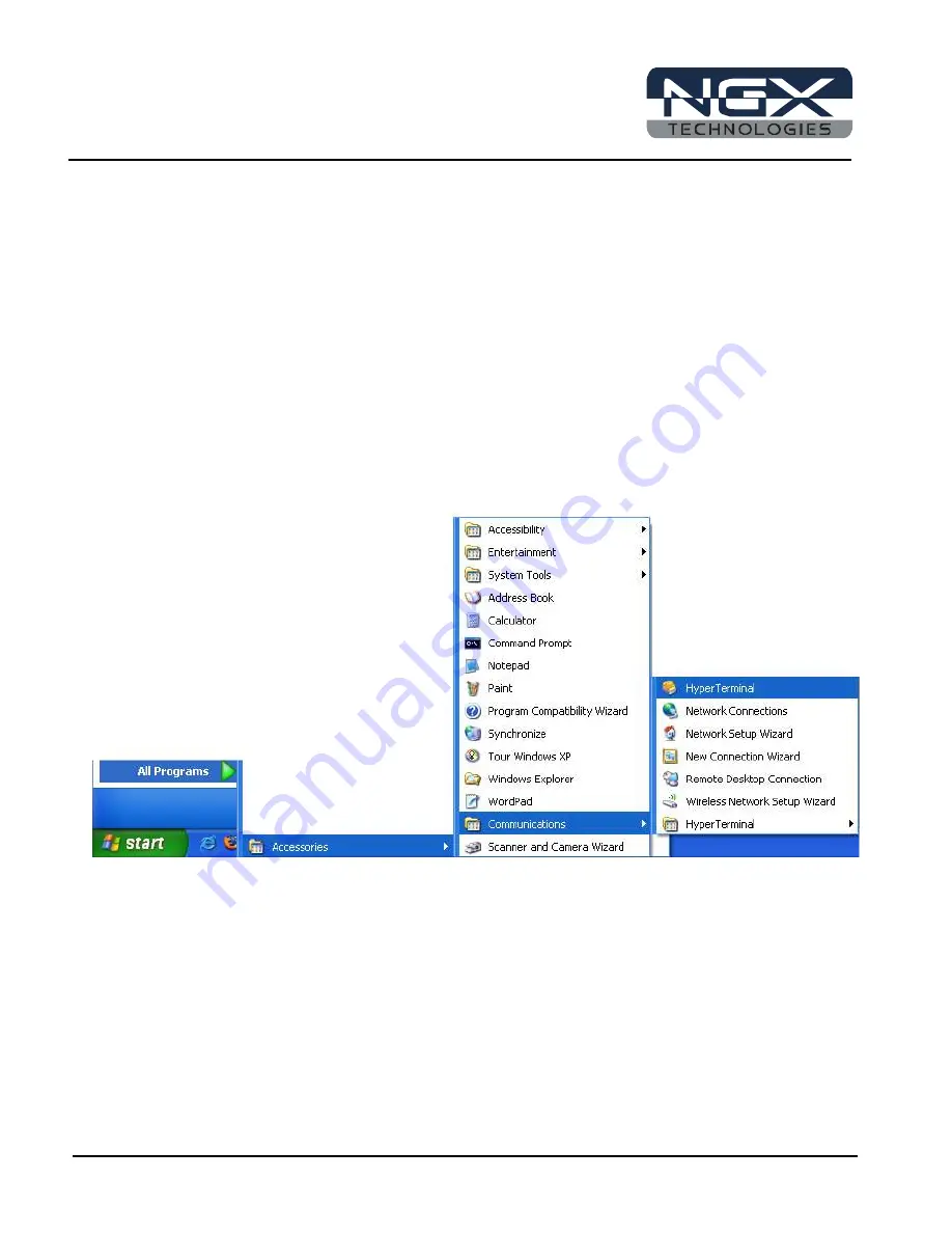
Connect jumpers to all pins of J6. Open the hyper terminal as shown in the below image.
To test the UART you can use either a full modem or half modem cable.
Click on hyper terminal a “Connection Description” window opens. Enter a name under the name tab e.g. BlueBoard
and click OK.


