Measurements and settings
Power Related Measurements
60
TemBreak
PRO
P_SE-UM-001-EN
– V1.2.0
Power factor sign convention
Power factor values (both PF and cosφ) are represented by the P_SE OCR
as having either a positive (+) or negative (-) sign depending on the sign
convention setting. The two sign conventions are dependent on either IEC or IEEE standards.
Changes to the power factor sign convention can be made using one or a combination of the below methods:
-
TPED
-
TPCM
TPED setting
TPCM setting
Default
“PF
S
ign convention”
IEEE:
IEEE Standard
IEC:
IEC Standard
Command ID: 105
“
Power factor sign convention
”
Hex 00 00:
IEEE Standard
Hex 00 01:
IEC Standard
IEEE Standard
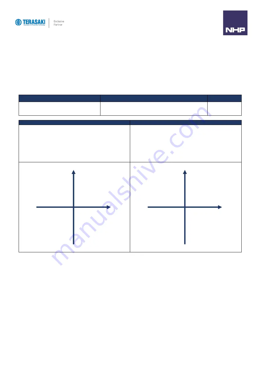
IEEE Convention
IEC Convention
The
sign for PF and cosφ is
dependent on both the flow direction of active
power and reactive power components of the load. This can be simplified
to whether the load is capacitive or inductive, independent of the active
power flow direction:
-
Inductive load, power factor is negative (-).
-
Capacitive load, power factor is positive (+).
The sign for PF and cosφ
is dependent on the flow direction of active
power (P), and is independent of the inductance or capacitance of the
load:
-
Power factor is positive (+) for normal active power flow. I.e.
active power flows into a load and energy is consumed.
-
Power factor is negative (-) for reverse active power flow. I.e.
active power flows out of the load and energy is generated.
-P
+P
+Q
-Q
Quadrant II
Capacitive
Active power
(−)
Reactive power (+)
PF/cos
ϕ
(+)
Quadrant I
Inductive
Active power
(+)
Reactive power (+)
PF/cos
ϕ
(−)
Quadrant III
Inductive
Active power
(−)
Reactive power
(−)
PF/cos
ϕ
(−)
Quadrant IV
Capacitive
Active power
(+)
Reactive power
(−)
PF/cos
ϕ
(+)
-P
+P
+Q
-Q
Quadrant II
Capacitive
Active power
(−)
Reactive power (+)
PF/cos
ϕ
(−)
Quadrant I
Inductive
Active power
(+)
Reactive power (+)
PF/cos
ϕ
(+)
Quadrant III
Inductive
Active power
(−)
Reactive power
(−)
PF/cos
ϕ
(−)
Quadrant IV
Capacitive
Active power
(+)
Reactive power
(−)
PF/cos
ϕ
(+)
Summary of Contents for Terasaki TemBreak PRO P SE Series
Page 106: ...106 TemBreak PRO P_SE UM 001 EN V1 2 0 Annex A Dimensions P160 Dimensions...
Page 107: ...Annex A Dimensions 107 TemBreak PRO P_SE UM 001 EN V1 2 0 P250 Dimensions...
Page 108: ...Annex A Dimensions 108 TemBreak PRO P_SE UM 001 EN V1 2 0 P400 Dimensions...
Page 109: ...Annex A Dimensions 109 TemBreak PRO P_SE UM 001 EN V1 2 0 P630 Dimensions...
Page 111: ...111 TemBreak PRO P_SE UM 001 EN V1 2 0 Annex C I2t Let Through Curves P160_SE...
Page 112: ...Annex C I2t Let Through Curves 112 TemBreak PRO P_SE UM 001 EN V1 2 0 P250_SE...
Page 113: ...Annex C I2t Let Through Curves 113 TemBreak PRO P_SE UM 001 EN V1 2 0 P400_SE...
Page 114: ...Annex C I2t Let Through Curves 114 TemBreak PRO P_SE UM 001 EN V1 2 0 P630_SE...
Page 115: ...115 TemBreak PRO P_SE UM 001 EN V1 2 0 Annex D Peak Let Through Curves P160_SE...
Page 116: ...116 TemBreak PRO P_SE UM 001 EN V1 2 0 P250_SE...
Page 117: ...117 TemBreak PRO P_SE UM 001 EN V1 2 0 P400_SE...
Page 118: ...118 TemBreak PRO P_SE UM 001 EN V1 2 0 P630_SE...
Page 121: ...121 TemBreak PRO P_SE UM 001 EN V1 2 0 This page is intentionally left blank...


