13
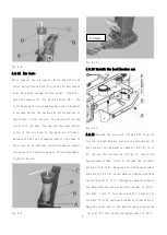
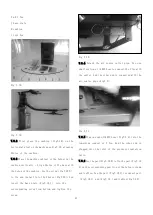
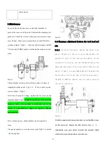
Fig 5-2
5.2 Demounting tire
Before operation, you must secure all the
weights has been detached from the wheel
and check the deflation of the tire.
When the column tilts back, you must secure
there is not any person behind the column.
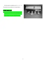
5.2.1Step down the pedal
(
Fig5-1 H
)
to tilt down the column.
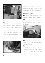
Step down the clamping jaw open/close pedal, the jaw will
open.
Use the tire press block to press the center of the rim and
then step down the clamping jaw open/close pedal to clamp
the tire on the turntable.
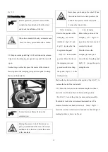
During the process to lock the rim, never
place your hand under the rim. The correct
method to fix is the tire is just at the center
of the turntable.
Outer clamping
Refer to the position of the
clamping jaw on the
turntable
(
Fig2-1 F and
Fig1-5
)
to place the tire.
Step down the pedal
(
Fig5-1 I
)
to the middle
position. Place the tire on
the clamping jaw and
press down the rim. Step
the pedal
(
Fig5-1 I
)
to the
limit position.
Inner clamping
Refer to the position of the
clamping jaw
(
Fig2-1 E
)
to position the tire to make it
completely closed.
Place the tire on the
clamping jaw and press
down the rim. Step the pedal
Fig5-1 I
)
to open the jaw to
clamp the rim.
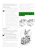
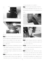
Position the lock press button at the position
(
Fig4-16 Y
)
to
release the lock of the tool arm M.
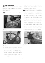
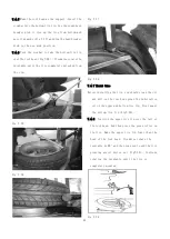
5.2.2 Move the tool arm downwards making the tool head
above the rim. Position the lock button at the position
(
Fig4-16 Z
)
to lock the entire tire demounting assembly.
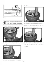
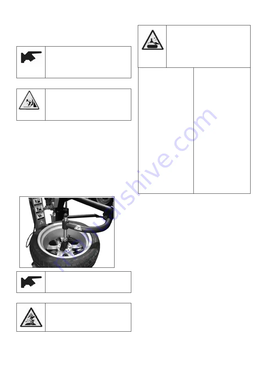
This kind of lock is the vertical and horizontal lock. The
distance from the tool head to the rim is 2mm
(
Fig5-3
)
.
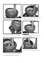
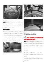
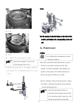
Insert the crowbar in between the bead and tool head (Fig5-5
)
making bead move above tool head.
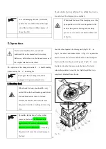
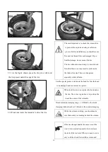
Never place your hand on the wheel. When
the column back to its work position, the
hand of the operator will be crashed in
between the tire and rim,
Secure the rim is firmly fixed on the
clamping jaw.
Summary of Contents for TC-1300
Page 1: ...3456789 C61CN...
Page 36: ...35...


