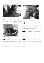
background image


Fig 4-5 

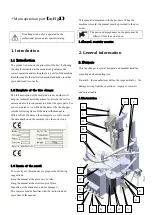
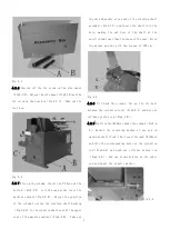
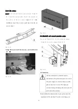
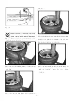
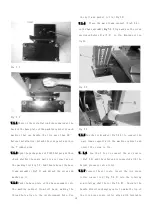
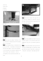
4.2.10 Connect the PU hose described in the step 

4.2.7 into the PU hose of the machine cabinet and 

insert into the Tee of the air source pipe(Fig4-7)
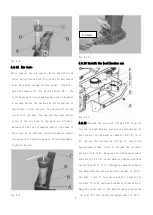


Fig 4-6 

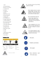
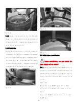
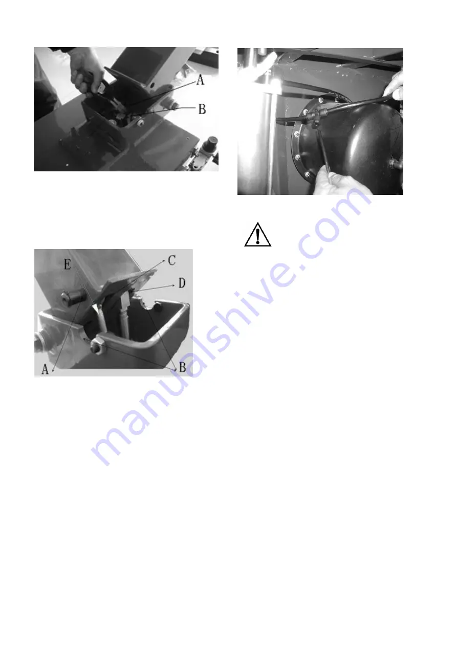
2.11 Mount the horizontal arm protective cover and 

detach the cap nut in the front(Fig4-8 A)and the 

protective cover fix screw at the back(Fig4-8 B)

and fix screw(Fig4-8 C) on the vertical shaft cap

(Fig4-8 D) and take out the vertical shaft cap. 


Fig 4-7


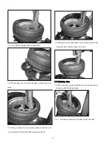
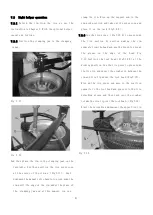
When you detach the vertical shaft cap, 

you should support the vertical shaft to prevent 

the slide of the vertical to cause the damage to 

the machine and injury to the person. 


4.2.12 Remove the package of the protective cover. 

Mount the vertical shaft spring(Fig4-9 D), vertical 

shaft cap and fix screw(Fig4-8 D)

(Fig4-8 C)and 

fix.


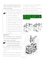
4.2.13 Adjust the set screw at the 2sides of the 

column. Release the nuts at the 2sides. Adjust the 

screw heads making the gap between them and the side 

plane of the column is 0.3mm(Fig4-10). Lock the 

nuts.


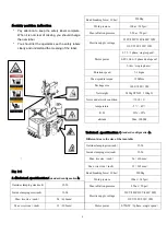
Summary of Contents for TC-1300

Page 1: ...3456789 C61CN...

Page 2: ...hooting 10 Electrical and pneumatic scheme Symbol and code printed In the manual the following symbol and code is convenient for reading Need careful operation Prohibition May cause the danger to the...

Page 3: ...achine to be the correct one 1 3 Remain of the manual To correctly use this manual we propose the following suggestions Keep the manual at the place easy to take Keep the manual at the moisture proof...

Page 4: ...o not reach any part of your body under the tool head When breaking bead the bead breaking blade will quickly move leftwards The operator should not stand between the blade and tire Note when break th...

Page 5: ...voltage 220V 380V230V 400V 3PH 110V 220V 230V 1PH Motor power 0 75 3phase single speed 0 85 1 1kw 3phase dual speed 1 1kw single phase Rotation speed 7 14rpm Max spindle torque 1200Nm Package size 14...

Page 6: ...forklift with the proper load Insert the fork as per the position indicated Fig3 1 Fig3 1 3 2 Unpacking Remove the cupboard and nylon bag used for protection Check whether the equipment is perfect to...

Page 7: ...knowledge of electrical The operators must under the special train Before installation you must carefully check the equipment list If you have any question immediately contact the dealer or our compan...

Page 8: ...er at one end of the rotation shaft assembly Fig4 1 A and insert the shaft into the hole making the end face of the shaft at the position 1mm lower than the plane of the seat Screw the washer and nut...

Page 9: ...D and take out the vertical shaft cap Fig 4 7 When you detach the vertical shaft cap you should support the vertical shaft to prevent the slide of the vertical to cause the damage to the machine and i...

Page 10: ...eed of the screw to be fast After adjustment tighten the nut Fig 4 9 Fig 4 10 4 2 15 Install the bead breaker arm Fig 4 11 4 2 16 Unscrew the stop nut Fig4 11 B from the top end of bead breaker piston...

Page 11: ...3 Fig 4 14 4 2 2Install and connect pressure gauge Via screw Fig4 15 B fix the pressure gauge Fig4 15 A on the column Fig4 15 C Fig 4 15 4 3Commision All the work related to electrical must be underta...

Page 12: ...se When rise up the pedal Fig4 17 K the turntable will rotate counterclockwise If the rotation direction of the turntable is different from the direction described in 4 4 change the wires at the 3 pha...

Page 13: ...if the clamping jaw at the open position it will be very dangerous to the hand of the operator During bead breaking process never contact your hand with the wall of the tire Lean the wheel against th...

Page 14: ...osition Place the tire on the clamping jaw and press down the rim Step the pedal Fig5 1 I to the limit position Inner clamping Refer to the position of the clamping jaw Fig2 1 E to position the tire t...

Page 15: ...ss the tire 5 2 4 Move the tool head downward to reach out the tool hook 5 2 5 until the tool hook deeply into the inside of the tire 5 2 6 Push upward the tool head handle valve to take back the tool...

Page 16: ...p the outside of the tire and press upward tool hook handle to hook up the tire 5 2 10Step down the main shaft rotate switch to make the turntable drive the tire clockwise rotate 5 3 Mounting tire 5 3...

Page 17: ...lloy rim These are dangerous especially while inflation Use the special grease to lubricate the bead for fear the bead to be damaged and convenient to operate When lock the rim do not place the hand u...

Page 18: ...sly follow the following instruction due to design of the tire changer does not consider the prevention the persons around from the accidental tire burst Tire burst will cause the serious injury or de...

Page 19: ...e lubrication Step down the pedal to the middle position Inflation Check the air pressure of the pressure gauge Continue inflation Check air pressure while inflation until the pressure reach the press...

Page 20: ...aking the thread hole align to the reinforcement hole Use the bolt and washer to fix Fig7 2 7 1 4 Place the main frame support Fig7 3 A on the base assembly Fig 7 3 Align and use the screw unscrewed b...

Page 21: ...me and then use the lock nut to tight 7 1 9 As Fig7 9 fix the cone bracket on the main frame and install the tire press cone on the bracket 7 1 10 Release the nut under the seat and screw the screw do...

Page 22: ...support arm to the non work position and take out the press cone and place it on the rack Fig7 9 A 7 2 3 Use the tire press Fig7 12 A to press down the tire section by section making the rim separate...

Page 23: ...ser at the tool head Fig51 Continue rotating the turntable until the operation is completed Fig 7 15 Fig 7 16 Fig 7 17 7 3 Right helper installation Before installation you must switch the power suppl...

Page 24: ...8 J into the corresponding screw from bottom and tighten the screw Fig 7 20 7 3 4 Detach the air source outlet pipe Use one small section of 8PU hose to connect the Y Tee with the outlet And the other...

Page 25: ...oves downward the seat will slide downward If without air leakage crawl and shake and all the parts running normally the installation is completed 7 4 Right helper operation 7 4 1 Prepare as per the u...

Page 26: ...e rim Fig 7 25 Fig 7 26 Fig 7 27 Fig 7 28 7 4 7 Mount tire Before installing the tire you should clean the oil and dirt on the rim And spread the lubrication oil on the upper and bottom tire lip First...

Page 27: ...is necessary for the correct operation and long service life of the machine If not regular maintenance the reliability and operation of the machine will be effected and cause the danger to the operato...

Page 28: ...of the factory It is prohibited to adjust air regulator without authorization If it is without power check whether the driving belt is loose Via special adjust screw on the motor rack Fig8 2 to detac...

Page 29: ...crew Fig8 3 B in the middle and meanwhile lock the horizontal arm 8 4Pedal switch repair Switch off the power supply and air source and remove the protective cover You can take out the entire pedal as...

Page 30: ...sealing washer The horizontal arm fault The vertical movement of the hexangular jamming The lock position of the quadric lock position not correct The lock position of the hexangular lock position no...

Page 31: ...e PE N L SA FU20A 3X1 5mm2 QC 9 5 7 11 1 3 0 1 2 10 6 8 12 2 4 LW5D 16 16A 500V 220V 1 1KW 1400rpm M 1ph U1 Z2 U2 V1 220V User installed power cable 3 1 5mm2 Tire changer internal wiring motor switch...

Page 32: ...31 380VElectrical scheme 4X1 5mm Tire changer3 phase motor 380V wiring diagram User installed power cable 4 1 5mm2 Tire changer internal wiring Motor switch LW5D 16 16A 500V...

Page 33: ...2 4 10 6 8 U2 U4 U3 U1 M 1 FU1 FU2 40A 3 Z2 PE U1 U2 U3 U4 Z1 Z2 220V 110V 2 4 6 11 5 2W30A TB 2506L 600V 25A 1 1KW 4P 110 220V 50 60HZ PE Customer configuration Motor switch 2W30A Motor switch LW5 4...

Page 34: ...33 Pneumatic scheme 70 20X262 70 20X262 186 20X150 70 20X310 70 20X310 186 20X150 Semi automatic pneumatic scheme Semi automatic burst inflation pneumatic scheme...

Page 35: ...34 It is absolutely prohibited to inflate on the tire changer The manufacturer has the right to modify the machine without notifying the buyer in advance...

Page 36: ...35...

Reviews: