background image

pg. 2


Assembly instructions for 5 foot climbing frame 


Materials provided

4 x 10ft posts cut at an angle of 40 degrees 

2 x 10ft posts cut at an angle of 60 degrees (with the top already prepared for the swing pole) 

1 x 10ft post for the swing pole 

2 x 1274mm posts  

2 x 6ftx4ft fence panels 

4 x ‘v’ boards for roof module 

1 x steps  

1 x 1460x1460 base 

3 x 1274mm 3”x1 ½” timber 

2 x 1460mm 3”x1 ½” timber 

4 sets of railings 

1 x rock wall 

Handgrips 

10ft slide 

6 x ‘o’ hooks 

Telescope  

Steering wheel 

Swing seats 

Hole covers 

Assortment of screws  


Summary of Contents for Double Climbing Frame

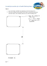
Page 1: ...e Climbing Frame Step A Lay out both bases with 8ft of spacing between them See Diagram X Once you are happy with the position of each base remove bases and follow instruction steps 1 8 on assembly in...

Page 2: ...ith the top already prepared for the swing pole 1 x 10ft post for the swing pole 2 x 1274mm posts 2 x 6ftx4ft fence panels 4 x v boards for roof module 1 x steps 1 x 1460x1460 base 3 x 1274mm 3 x1 tim...

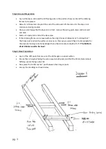
Page 3: ...f the climbing frame is on a level surface then dig 4 holes of diameter 12 and depth 12 The tricky part is when the surface is uneven in this case you would have to compensate for the slope by making...

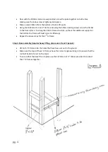
Page 4: ...tructure without this additional support at the bottom the frame will twist once it is lifted up Repeat the above steps for the 2nd H frame Step 3 Base assembly requires heavy lifting please use at le...

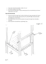
Page 5: ...ss posts Step 4 Side rails assembly There are 2 open and 2 closed rails The open ones are for the steps and slide and the closed ones are for the rock module and swing module They should fit tightly i...

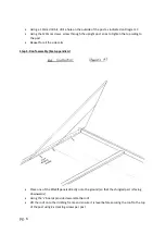
Page 6: ...iling to the post Repeat for all the side rails Step 5 Roof assembly See Appendix A Place one of the 6ftx4ft panels directly onto the ground so that the shingled part is facing downwards Using the v b...

Page 7: ...rees on a flat surface Place the ends together so that it forms a v shape Using the 200mm index screws tighten the ends together Measure down from the top of the v post 1100mm to both posts and place...

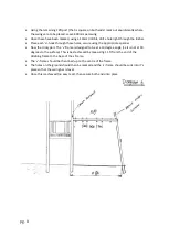
Page 8: ...ropriate spanner Now the tricky part The v frame is designed to be at a 10 degree angle i e it is not at 90 degrees to the surface This is best achieved by measuring 11 ft from the end of the climbing...

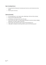
Page 9: ...ending on the slope of your surface They are secured using decking screws Grab handles are then placed on the top of the steps The rock wall is also to be cut or dug into place typically the rock wall...

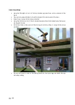
Page 10: ...ntre point of the base Screw these in using 120mm screws provided Using the 1274mm 3x1 1 12 that is doubled up place these horizontally below the base as per diagram G below Drill 19mm holes on the ou...

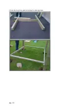
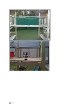
Page 11: ...pg 11 Photos that might be useful in building the climbing frame...

Page 12: ...pg 12...

Page 13: ...pg 13...

Reviews: