14
|
ni.com
|
NI PXIe-5624R Calibration Procedure
5.
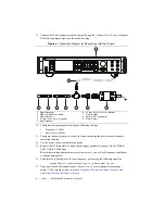
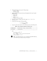
Configure the NI 5624R with the following settings:
•
DDC mode
•
Center frequency: The first frequency listed in the
NI 5624R Center Frequency (MHz)
column in Table 3.
•
I/Q rate: 500 MHz
•
Dither: On (High)
6.
Configure the signal generator with the following settings:
•
Frequency: The first frequency listed in the
Generator Start Frequency (MHz)
column
in Table 3
•
Power level: 4 dBm
7.
Configure the power sensor to correct for the current frequency of the signal generator
using the power sensor frequency correction function.
8.
Use the power sensor to measure the power. Record the result as
measured input power
.
Note
Power sensor readings are in dBm, not watts.
9.
Calculate the
corrected input power
using the following equation:
corrected input power
=
measured input power
+
splitter balance
Tip
Find the splitter balance by using the appropriate data points from the
Characterizing Power Splitter Balance
10. Perform an acquisition and measure the tone present at the frequency generated by the
signal generator.
11. Calculate the
absolute amplitude accuracy
using the following equation:
absolute amplitude accuracy = NI 5624R input power – corrected input power
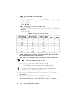
Table 3.
Configured Center Frequencies
NI 5624R Center
Frequency (MHz)
Generator Start
Frequency (MHz)
Generator Stop
Frequency (MHz)
Step Size (MHz)
225
25
425
5
500
300
700
5
800
600
995
5
1200
1005
1400
5
1500
1300
1700
5
1800
1600
1975
5

