18
|
ni.com
|
NI PXIe-5624R Calibration Procedure
4.
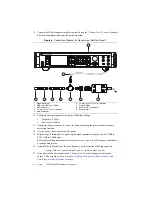
Connect the 6 dB attenuator SMA (m) connector directly to the NI 5624R IF IN front panel
connector.
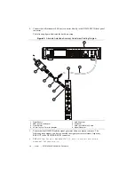
The following figure illustrates the hardware setup.
Figure 6.
Absolute Amplitude Accuracy Adjustment Cabling Diagram
5.
Ensure that the NI 5624R and the signal generator share a common reference. The
following steps assume you have connected the signal generator reference frequency
REF OUT to the NI 5624R REF IN connector.
6.
Call
niIFDig Group A ExternalCal v1 Host.lvclass:Initialize
External Calibration.vi
.
1
Power Sensor
2
SMA (m)-to-N (f) Adapter
3
Power Splitter
4
3.5 mm (m)-to-3.5 mm (m) Adapter
5
6 dB Attenuator
6
NI 5624R
7
SMA (m)-to-SMA (m) Cable
8
Signal Generator
ACCESS
ACTIVE
4
5
7
3
2
1
6
8


