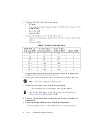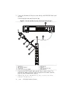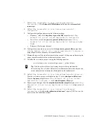
NI PXIe-5624R Calibration Procedure
|
© National Instruments
|
17
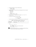
4.
Call
niIFDig ExternalCal v1 Host.lvclass:Clock FrequencyCal.vi
. Wire
the frequency of the signal generator to the
actual frequency (Hz)
input.
5.
Call
niIFDig ExternalCal v1 Host.lvclass:Close External
Calibration.vi
. Set the
write calibration to hardware?
input to TRUE to store the
results to the NI 5624R flash memory.
Adjusting Absolute Amplitude Accuracy
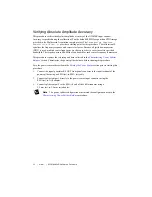
This procedure measures the response of the IF IN signal path of the NI 5624R.
This procedure requires the test setup and data collected in the
section. Characterize the power splitter balance before running this procedure.
Make sure to use the power splitter balance characterization data for the correct frequency, as
the following frequencies are excluded from the adjustment procedure due to harmonics aliasing
back on to the fundamental and disrupting the measurement:
•
200 MHz
•
250 MHz
•
400 MHz
•
500 MHz
•
600 MHz
•
750 MHz
•
800 MHz
•
1.2 GHz
•
1.5 GHz
•
1.6 GHz
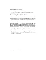
Zero the power sensor as described in the
section prior to starting this
procedure.
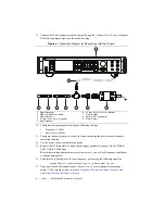
1.
Connect the signal generator RF OUT front panel connector to the input terminal of the
power splitter using an SMA (m)-to-SMA (m) cable.
2.
Connect splitter output 1 directly to the power sensor input connector using an
SMA (m)-to-N (f) adapter.
3.
Connect the splitter output 2 to the SMA (f) end of the 6 dB attenuator using a
3.5 mm (m)-to-3.5 mm (m) adapter.
Note
The power splitter configuration must match the configuration used in the
Characterizing Power Splitter Balance
procedure.


