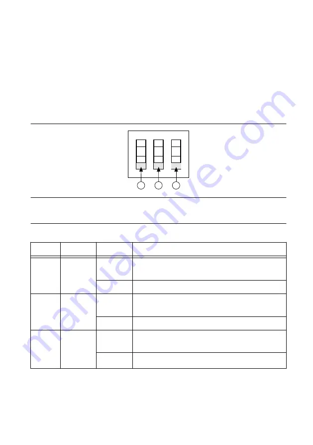
DIP switch #1 (on the left) controls the chassis fan mode. Set this switch in the off position
(down in the following figure) to select Auto mode. Set this switch in the on position (up in
the following figure) to select High mode.
DIP switch #2 (in the center) controls the chassis Inhibit Mode. Set this switch in the off
position (down in the following figure) to select Default mode. Set this switch in the on
position (up in the following figure) to select Manual mode.
DIP switch #3 (on the right) controls the host power up mode. Set this switch in the off
position (down in the following figure) to select Default mode. Set this switch in the on
position (up in the following figure) to select Manual mode.
Figure 11. PXIe-1090 DIP Switches
1
2
3
ON
1. Switch #1 (Fan)
2. Switch #2 (Inhibit)
3. Switch #3 (Host Power)
Table 7. DIP Switch States
Location
Switch
State
Description
1
Fan
Off (Down) Set chassis fan mode to Auto. Refer to the
Fan Mode
section for information.
On (Up)
Set chassis fan mode to High.
2
Inhibit
Off (Down) Set chassis inhibit mode to Default. Refer to the
Inhibit
Mode
section for information.
On (Up)
Set chassis inhibit mode to Manual.
3
Host Power Off (Down) Set host power up mode to Default. Refer to the
Default Host Power Up Mode
section for information.
On (Up)
Set host power up mode to Manual.
Inhibit Mode
The PXIe-1090 chassis supports operation in two inhibit modes. Use Default mode when you
desire normal Power Inhibit switch functionality. In Default mode, when no host is connected
16
|
ni.com
|
PXIe-1090 User Guide


