background image

Table 2. NI Power Supplies

Power Supply

Part Number


NI PS-15 Industrial Power Supply
(24 VDC, 5 A, 100 VAC to 120 VAC/200 VAC to 240 VAC input)

781093-01

NI PS-10 Desktop Power Supply
(24 VDC, 5 A, 100 VAC to 120 VAC/200 VAC to 240 VAC input)

782698-01

What to Do

Complete the following steps to connect a power supply to the cRIO-9082.
1.

Ensure that your power supply is powered off.

2.

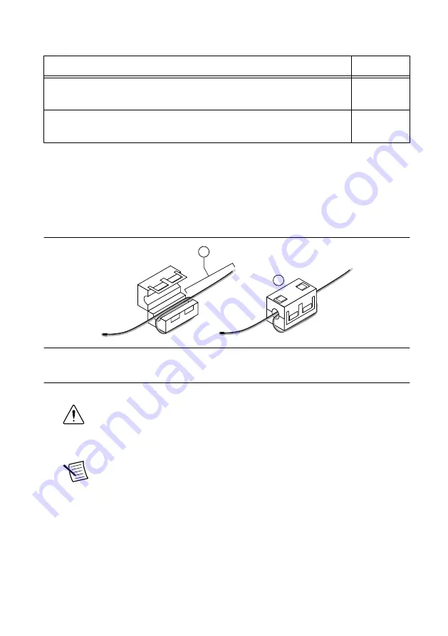
Install the ferrite on the negative and positive leads of the power supply, as shown in the
following figure.

Figure 2. Installing a Ferrite on the Power Leads

2

1

1. Pass the leads through the ferrite twice, leaving 50 mm to 75 mm (2 in. to 3 in.) between the ferrite and

the end of the leads.

2. Close the ferrite around the leads.

3.

Remove the power connector from the cRIO-9082.

Caution


Do not tighten or loosen the terminal screws on the power connector

while the cRIO-9082 is powered on.

4.

Connect the primary power supply and optional secondary power supply to the power
connector.

Note


The C terminals are internally connected to each other.

5.

Tighten the terminal screws on the power connector to 0.20 N · m to 0.25 N · m
(1.8 lb · in. to 2.2 lb · in.) of torque.

6.

Install the power connector on the front panel of the cRIO-9082.

7.

Tighten the power connector screw flanges to 0.20 N · m to 0.25 N · m (1.8 lb · in. to
2.2 lb · in.) of torque.

8.

Power on the primary power supply and optional secondary power supply.

8

  | 

ni.com

  | 

NI cRIO-9082 Getting Started Guide

Summary of Contents for cRIO-9082

Page 1: ...this document Product misuse can result in a hazard You can compromise the safety protection built into the product if the product is damaged in any way If the product is damaged return it to NI for...

Page 2: ...urope and Internationally The cRIO 9082 has been evaluated as Ex nA IIC T4 Gc equipment under DEMKO 07 ATEX 0626664X and is IECEx UL 14 0089X certified Each device is marked II 3G and is suitable for...

Page 3: ...cation for a product visit ni com certification and search for the LR certificate or look for the Lloyd s Register mark on the product Caution In order to meet the EMC requirements for marine applicat...

Page 4: ...evice with Power Connector 2 Ferrite 3 cRIO Device Drivers Media 4 Getting Started Guide Installing Software on the Host Computer Before using the cRIO 9082 you must install the following application...

Page 5: ...e C Series module 3 Align the C Series module with a slot and seat it in the slot until the latches lock in place Removing C Series Modules Verify that power is not connected to the I O connector s on...

Page 6: ...the grounding electrode system of the facility What to Use Ring lug Wire 1 6 mm2 14 AWG or larger Screwdriver Phillips 2 What to Do Complete the following steps to ground the cRIO 9082 1 Attach the r...

Page 7: ...a primary power input V1 and a secondary power input V2 The POWER LED on the cRIO 9082 indicates which power input is in use as shown in the following table Table 1 POWER LED Indicators LED Color LED...

Page 8: ...m 2 in to 3 in between the ferrite and the end of the leads 2 Close the ferrite around the leads 3 Remove the power connector from the cRIO 9082 Caution Do not tighten or loosen the terminal screws on...

Page 9: ...g the cRIO 9082 to a Network Connect the cRIO 9082 to an Ethernet network using RJ 45 Ethernet port 1 on the controller front panel Use a standard Category 5 CAT 5 or better shielded twisted pair Ethe...

Page 10: ...the IP Settings section then click Apply Note For information about configuring network settings refer to the Configuring Network Settings book of the MAX Remote Systems Help In MAX click Help Help To...

Page 11: ...settings When you reboot the controller with the IP RESET switch in the ON position the controller attempts to connect to the network using DHCP If the controller is unable to obtain an IP address it...

Page 12: ...Modify the VI as necessary to solve the memory usage issue Continuously Flashing The chassis has detected an unrecoverable error Contact National Instruments Continuously Flashing or Solid The device...

Page 13: ...extended warranty and other services Visit ni com register to register your NI product Product registration facilitates technical support and ensures that you receive important information updates fro...

Page 14: ...You can find information about end user license agreements EULAs and third party legal notices in the readme file for your NI product Refer to the Export Compliance Information at ni com legal export...

Reviews: