background image

Appendix 4

BIOS Configuration and System Recovery

NI EVS-1464 Series User Manual

4-4

ni.com

Note

Certain real-time applications may require you to disable this setting to reduce loop 

time jitter. When the device is configured to boot LabVIEW Real-Time, legacy USB 
support is automatically disabled.

SATA Mode

—Specifies whether the SATA controller operates in 

Enhanced

 or 

Compatible

 mode. 

Enhanced

 mode provides the 

advanced features of a SATA controller, while 

Compatible

 mode 

provides legacy backwards compatibility with standard ATA for 
operating systems that do not natively support SATA. The default 
setting is 

Enhanced

.

Note

When the device is configured to boot LabVIEW Real-Time, SATA Mode is 

automatically configured for 

Compatible

 mode.

AHCI Configuration

—Specifies whether AHCI mode is 

Enabled

 or 

Disabled

 for the SATA port. Use this setting to disable AHCI mode for 

non-compatible operating systems. The default setting is 

Enabled

.

Multi-Core Processing

—Specifies whether or not the second core 

processor is enabled. The default setting is 

Enabled

.

Intel

®

 Virtualization Technology

—Allows the system to run 

multiple operating systems and applications in separate partitions. 
The default setting is 

Enabled

.

Force IGD Primary

—Specifies how the BIOS prioritizes video 

controllers when external video cards are present in the system. During 
POST, only one device can act as the video display device. When set 
to 

Enabled

, the BIOS allows the integrated graphics device to remain 

the video display device. When set to 

Disabled

, the BIOS allows an 

external graphics card, if present, to act as the default video display 
device. Note that even when set to 

Disabled

, the integrated graphics 

device still acts as the video display device if it is the only one available 
in the system. The default setting is 

Disabled

.

PCI Menu

Normally, you do not need to modify these settings. However, other 
sections of this manual may indicate that modifications are necessary 
and may lead to unpredictable behavior.

APIC Routing

—This menu item is valid only for Windows 

XP/2000/Vista or other modern operating systems. Select 

Enabled

 to 

initialize the IOAPIC and local APIC in uniprocessor mode. Select 

Disabled

 to use the legacy PIC for interrupt routing. The default 

setting is 

Enabled

.

Summary of Contents for EVS-1464 Series

Page 1: ...NI Vision NI EVS 1464 Series User Manual July 2010 372486C 01...

Page 2: ...banon 961 0 1 33 28 28 Malaysia 1800 887710 Mexico 01 800 010 0793 Netherlands 31 0 348 433 466 New Zealand 0800 553 322 Norway 47 0 66 90 76 60 Poland 48 22 328 90 10 Portugal 351 210 311 210 Russia...

Page 3: ...ritten consent of National Instruments Corporation National Instruments respects the intellectual property of others and we ask our users to do the same NI software is protected by copyright and other...

Page 4: ...e encouraged to try to correct the interference by one or more of the following measures Reorient the antenna of the receiver the device suffering interference Relocate the transmitter the device gene...

Page 5: ...dule 1 3 NI Vision Development Module 1 4 Camera Interface Overview 1 5 IEEE 1394 1 5 Acquisition Window Control 1 5 GigE Vision 1 6 Chapter 2 LED Indicators DIP Switches and Connectors LEDs and DIP S...

Page 6: ...Input 5 as a Latch 3 9 General Purpose I O 3 10 General Purpose Inputs 3 10 General Purpose Outputs 3 10 I O for Fault Conditions 3 10 Shutdown 3 11 Watchdog Timer 3 12 Considerations When Connecting...

Page 7: ...iginal Software 4 9 Restoring Software on the NI EVS 1464 4 9 Restoring Software on the NI EVS 1464RT 4 9 Appendix A Specifications Appendix B Mounting Information Appendix C Cabling Options Appendix...

Page 8: ...is icon denotes a caution which advises you of precautions to take to avoid injury data loss or a system crash When this symbol is marked on a product refer to the product documentation for informatio...

Page 9: ...igating to Start All Programs National Instruments Vision Documentation NI IMAQ IO Getting Started with the NI EVS 1464RT Contains important safety information and installation and configuration instr...

Page 10: ...erence information about LabVIEW VIs functions palettes menus and tools Getting Started with LabVIEW Use this manual as a tutorial to familiarize yourself with the LabVIEW graphical programming enviro...

Page 11: ...atures a 1 GB solid state drive and a real time operating system including real time support for connected cameras and image processing applications Both NI EVS 1464 series systems include IEEE 1394b2...

Page 12: ...ent environment NI Vision Acquisition Software performs all functions required for acquiring and saving images but does not perform image analysis Refer to the Application Development Software Overvie...

Page 13: ...to easily configure and benchmark a sequence of visual inspection steps as well as deploy the visual inspection system for automated inspection With Vision Builder AI you can perform powerful visual...

Page 14: ...evelopment Module imaging novices and experts can program the most basic or complicated image applications without knowledge of particular algorithm implementations NI Vision Assistant which is includ...

Page 15: ...ing IEEE 1394 hubs NI EVS 1464 series systems can acquire images from IEEE 1394 cameras conforming to the IIDC 1394 based Digital Camera Specification Version 1 30 and later The IEEE 1394 bus provides...

Page 16: ...ates than USB USB 2 IEEE 1394a and IEEE 1394b GigE Vision networks can acquire images from multiple cameras however all cameras on the network share the same bandwidth While Gigabit Ethernet is a stan...

Page 17: ...Switch 4 Audio In Connector 5 Audio Out Connector 6 Safe Mode IP Reset No App User 1 CF Master Slave Switches 7 User 2 User 1 HDD Power LEDs 8 CompactFlash Slot 9 Power Supply Connector 10 Grounding...

Page 18: ...an external power supply provides power for the isolated outputs on the 44 pin D SUB connector DIP Switches The front panel of a NI EVS 1464 series system features the following switches RESET Recess...

Page 19: ...on Video DVI I 24 pin DSUB Intel GMA 950 Serial 9 pin DSUB 16550 RS 232 serial port Ethernet LAN RJ45 10 100 1000 Ethernet connection USB four ports USB 4 pin Series A stacked receptacle Hi Speed USB...

Page 20: ...connector signals Figure 2 2 DVI I Connector Location and Pinout Table 2 2 DVI I Connector Signals Pin Signal Name 1 TMDS Data2 2 TMDS Data2 3 TMDS Data2 4 Shield 4 Reserved 5 Reserved 6 DDC Clock SC...

Page 21: ...5 V Power 15 Ground for 5 V 16 Hot Plug Detect 17 TMDS Data0 18 TMDSData0 19 TMDS Data0 5 Shield 20 Reserved 21 Reserved 22 TMDS Clock Shield 23 TMDS Clock 24 TMDS Clock C1 Analog Red C2 Analog Green...

Page 22: ...serial connector signal Figure 2 3 RS 232 Serial Connector Location and Pinout Table 2 3 RS 232 Serial Connector Signals Pin Signal Name Signal Description 1 DCD Data Carrier Detect 2 RXD Receive Dat...

Page 23: ...Time you must use the primary network connector the port on the left for discovery and configuration Figure 2 4 Ethernet Connector Location and Pinout Note The Ethernet controller can perform automati...

Page 24: ...Color LED State Condition Left Green Off LAN link is not established On steady state LAN link is established On brighter and pulsing The controller is communicating with another computer on the LAN Ri...

Page 25: ...el which provides I O expansion and options for removable storage Figure 2 6 shows the location and pinouts for the CompactFlash slot on the NI EVS 1464 series system Table 2 7 lists and describes the...

Page 26: ...a 3 3 D4 Data 4 4 D5 Data 5 5 D6 Data 6 6 D7 Data 7 7 CE1 Card Enable 1 8 A10 Address 10 9 OE Output Enable 10 A9 Address 9 11 A8 Address 8 12 A7 Address 7 13 VCC 5 V 14 A6 Address 6 15 A5 Address 5 1...

Page 27: ...d 35 IOWR I O Write 36 WE Write Enable 37 READY RDY IREQ Ready Busy Interrupt Request 38 VCC 5 V 39 CSEL Cable Select 40 VS2 RFU 41 RESET Reset 42 WAIT Wait 43 INPACK Input Acknowledge 44 REG Register...

Page 28: ...nector Signals Pin Side B Connector Side A Connector Name Description Name Description 1 12V 12 V Power PRSNT 1 Hot Plug Presence Detect 2 12V 12 V Power 12V 12 V Power 3 RSVD Reserved 12V 12 V Power...

Page 29: ...t Mechanical Key 12 RSVD Reserved GND Ground 13 GND Ground REFCLK Reference Clock Differential Pair 14 HSOp 0 Transmitter Lane 0 Differential Pair REFCLK 15 HSOn 0 GND Ground 16 GND Ground HSIp 0 Rece...

Page 30: ...I EVS 1464 series system Table 2 10 lists and describes the power connector signals Figure 2 9 Power Connector Location and Pinout Table 2 9 Audio Connector Signals Pin Signal Name Signal Description...

Page 31: ...connectors on the NI EVS 1464 series system Figure 2 10 IEEE 1394b Location The NI EVS 1464 series system provides two direct connect IEEE 1394b bilingual connectors which support IEEE 1394a and IEEE...

Page 32: ...ted outputs is present For easy connection to the digital I O connector use the National Instruments digital I O cable and the NI Vision I O Terminal Block and Prototyping Accessory Note The accessori...

Page 33: ...onnector on the NI EVS 1464 series system and the 37 pin terminal block Table 2 11 Signal Connections 44 Pin D SUB on NI EVS 1464 Pin Number 37 Pin Terminal Block Number Signal Name Primary Function A...

Page 34: ...ator output General purpose output 8 6 C Common mode signal of the NI EVS 1464 device main power 9 NC TRIG 2 TTL Output 8 Pulse generator output General purpose output 10 17 Viso Isolated power 11 NC...

Page 35: ...purpose output 19 21 TTL Output 5 General purpose output 20 22 C Common mode signal of the NI EVS 1464 device main power 21 23 TTL Output 6 General purpose output 22 24 TTL Output 7 General purpose o...

Page 36: ...4 14 ISO Input 4 Input port Data 4 35 15 ISO Input 5 Input port latch Data 5 Pulse generator trigger input 36 28 Ciso Isolated common mode signal 37 25 ISO Input 6 Quadratureencoder Phase A General pu...

Page 37: ...ut Trigger Change Detector General purpose input 44 31 ISO Input 11 User shutdown General purpose input TRIG 0 TRIG 1 and TRIG 2 are not available on the 37 pin terminal block or the NI Vision I O Ter...

Page 38: ...PGA which has been configured with the functionality required for most common machine vision tasks If the factory configured functionality does not fulfill your requirements the FPGA is user configura...

Page 39: ...view these examples TTL Inputs and Outputs TTL is a fast switching 5 V digital signaling standard commonly used for applications that require high precision such as camera triggering TTL inputs and o...

Page 40: ...hen using custom cabling Alternatively Viso can be supplied directly to the 37 pin terminal block and to the NI Vision I O Terminal Block and Prototyping Accessory with the 44 pin to 37 pin NI cable N...

Page 41: ...RIG 0 ISO Input 5 ISO Input 8 11 35 40 15 27 Quadrature Encoder Input 1 ISO Input 6 ISO Input 7 37 38 25 26 External Shutdown Control Input 1 ISO Input 11 44 31 Product Selection Port Input 1 ISO Inpu...

Page 42: ...ut 5 can alternatively function as a latch for the product selection port Timed Pulse Output NI EVS 1464 series systems are capable of timed pulse output on six different digital outputs which provide...

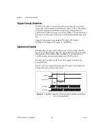
Page 43: ...se The assertion edge is configurable based on the trigger polarity parameter It then generates one pulse and rearms to wait for the next trigger In either case the pulse output generation stops and r...

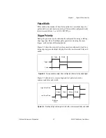
Page 44: ...ing Even if multiple pulse generators are using the same trigger each can have different polarities Figure 3 2 shows the output of a pulse generator configured to look for a rising edge trigger and ou...

Page 45: ...de TTL Input 0 TTL Input 1 ISO Input 8 ISO Input 9 ISO Input 10 and TRIG 0 Quadrature Encoder The quadrature encoder uses ISO Input 6 for its Phase A input and ISO Input 7 for its Phase B input Encode...

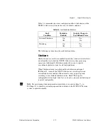
Page 46: ...rnatively a PLC with information about which part is being inspected can drive the product selection port of the NI EVS 1464 series system Using ISO Input 5 as a Latch You can configure the product se...

Page 47: ...our inspection General Purpose Outputs The primary difference between general purpose outputs and timed pulse outputs is that the timing of general purpose outputs is controlled by software rather tha...

Page 48: ...s for all fault conditions When Shutdown mode is enabled and the shutdown input signal ISO Input 11 turns off the NI EVS 1464 series system registers an external shutdown condition When a fault occurs...

Page 49: ...ed upon to send notification to the host Indicator Only This option sends the expiration signal back to the development machine through software True indicates an expired watchdog timer False indicate...

Page 50: ...an isolated input to a sourcing output device as shown in the following figure Refer to Getting Started with the NI EVS 1464 or Getting Started with the NI EVS 1464RT for information about switching...

Page 51: ...ital output circuit sources current to external loads as shown in Figure 3 6 Caution Do not draw more than 100 mA from 24 V or 30 V isolated outputs Do not draw more than 50 mA from 5 V isolated outpu...

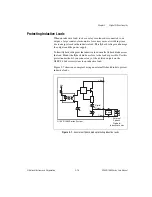
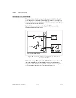
Page 52: ...utputs and the power supply To limit flyback voltages at the inductive load install a flyback diode across the load Mount the flyback diode as close to the load as possible Use this protection method...

Page 53: ...shows connections to the 44 pin D SUB connector that minimize transmission line effects Figure 3 8 Connections to the 44 pin D SUB connector that minimize transmission line effects When connecting to...

Page 54: ...t settings in the Clearing System CMOS section In general do not change a setting unless you are absolutely certain what it does or National Instruments directs you to do so Entering BIOS Setup To sta...

Page 55: ...ting is stored in a battery backed real time clock You can also change this setting from within Measurement Automation Explorer MAX or NI Vision Builder AI System Date Changes the system date The syst...

Page 56: ...ting to bring up the Integrated Peripherals submenu For information about the menu items within this submenu refer to the Integrated Peripherals Submenu section Quick Boot Mode Decreases system boot t...

Page 57: ...fault setting is Enabled Intel Virtualization Technology Allows the system to run multiple operating systems and applications in separate partitions The default setting is Enabled Force IGD Primary Sp...

Page 58: ...he switches select Use Hardware Switch for each option Boot Configuration Selects whether the device should boot LabVIEW Real Time LabVIEW Real Time Safe Mode or an installed OS such as Windows XP Res...

Page 59: ...vice This setting does not prevent boot sector modification by 32 bit operating system drivers that access the hard disk directly The default is No Boot Menu This screen displays the boot order of dev...

Page 60: ...ail to boot Discard Changes Discards any changes made to BIOS settings Unlike Exit Discarding Changes however the BIOS setup continues to be active Save Changes Stores any changes made to BIOS setting...

Page 61: ...d move the jumper back to pins 2 3 8 Reconnect the 2 5 in HDD cable noting the pin 1 orientation 9 Reattach the bottom plate to the chassis with the eight retaining screws 10 Turn over the device so t...

Page 62: ...cess the hard drive based recovery program press and hold F4 during the boot process Operating system installation discs are available upon request Contact National Instruments to request an operating...

Page 63: ...RT P N 194966A 031L 2 1 GB NI EVS 1464RT P N 194966B 031L or later 2 2 GB Integrated hard drive NI EVS 1464 80 GB minimum serial ATA NI EVS 1464RT 1 GB minimum parallel ATA solid state Integrated grap...

Page 64: ...tage 10 VDC to 30 VDC Power excluding cameras 50 W maximum IEEE 1394 bus power 18 W maximum shared by both ports Caution Do not draw more than 100 mA from 24 V or 30 V isolated outputs Do not draw mor...

Page 65: ...utput voltage range 0 V to 5 V Maximum pulse rate 2 MHz Optically Isolated Inputs and Outputs Isolated Current Sinking Inputs Number of channels 13 Input voltage range 0 V to 30 V Input ON voltage 3 5...

Page 66: ...m 24 V isopower 100 mA maximum 30 V isopower 100 mA maximum Maximum pulse rate 10 kHz maximum load resistance 100 k Minimum pulse generated 100 s Reverse polarity protection Yes IEEE 1394 Interface Nu...

Page 67: ...ore powering on the controller again Storage Environment Ambient temperature range 40 C to 70 C IEC 60068 2 1 and IEC 60068 2 2 Relative humidity range 5 to 95 noncondensing IEC 60068 2 56 Shock and V...

Page 68: ...issions AS NZS CISPR 11 Group 1 Class A emissions FCC 47 CFR Part 15B Class A emissions ICES 001 Class A emissions Note For the standards applied to assess the EMC of this product refer to product lab...

Page 69: ...the product life cycle all products must be sent to a WEEE recycling center For more information about WEEE recycling centers National Instruments WEEE initiatives and compliance with WEEE Directive...

Page 70: ...d clearance information for the NI EVS 1464 series device Caution Do not position the NI EVS 1464 series device with the heat sinks resting on any surface Doing so may cause the NI EVS 1464 series dev...

Page 71: ...B 2 ni com Figure B 1 Top View of the NI EVS 1464 Series Device with Dimensions 200 00 mm 7 874 in 10 51 mm 0 414 in 4 00 mm 0 157 in 189 00 mm 7 441 in NATIONAL INSTRUMENTS 189 00 mm 7 441 in 5 50 mm...

Page 72: ...ser Manual Figure B 2 Front View of the NI EVS 1464 Series Device with Dimensions Figure B 3 Side View of the NI EVS 1464 Series Device with Dimensions 163 72 mm 6 446 in 110 00 mm 4 331 in 5 00 mm 0...

Page 73: ...ng Information NI EVS 1464 Series User Manual B 4 ni com Figure B 4 Air Circulation Clearance for the NI EVS 1464 Series Device 152 4 mm 6 0 in 152 4 mm 6 0 in 152 4 mm 6 0 in DIGITAL I O IEEE 1394b I...

Page 74: ...hernet performance CAT 5e and CAT 6 Ethernet cables adhere to higher electrical standards required for Gigabit Ethernet communication CAT 5 cables are not guaranteed to meet the necessary electrical r...

Page 75: ...t and prototype digital I O applications The NI Vision I O Terminal Block and Prototyping Accessory provides screw terminals for easy connections and LEDs for each signal Note TRIG 0 TRIG 1 and TRIG 2...

Page 76: ...could damage the device How do I repair a corrupted system CMOS Complete the following steps to load BIOS defaults 1 Enter the BIOS setup program as described in the Entering BIOS Setup section of Cha...

Page 77: ...n of Chapter 4 BIOS Configuration and System Recovery for information about restoring factory installed software How do I install an operating system NI EVS 1464 series systems include a preinstalled...

Page 78: ...system Caution Do not insert or remove the CompactFlash card while the system is powered on Doing so may cause data loss and in some cases the drive may need reformatting Third party cards may requir...

Page 79: ...d starts the NI EVS 1464RT device in safe mode and does not launch the embedded LabVIEW Real Time engine Why is my NI EVS 1464RT device not listed as a target in MAX or in Vision Builder AI Verify tha...

Page 80: ...EVS 1464RT device by pressing the RESET button on the NI EVS 1464RT device for at least two seconds Why does MAX or Vision Builder AI report that no software is installed to the NI EVS 1464RT Install...

Page 81: ...ard Service Program Membership This program entitles members to direct access to NI Applications Engineers via phone and email for one to one technical support as well as exclusive access to on demand...

Page 82: ...compatibility EMC and product safety You can obtain the DoC for your product by visiting ni com certification If you searched ni com and could not find the answers you need contact your local office...

Page 83: ...n nano 10 9 micro 10 6 m milli 10 3 k kilo 103 M mega 106 G giga 109 T tera 1012 Symbols Degrees Ohms Percent A A Amperes acquisition window The image size specific to a video standard or camera resol...

Page 84: ...mputer s hardware resources bus The group of conductors that interconnect individual circuitry in a computer such as the PCI bus typically the expansion vehicle to which I O or other devices are conne...

Page 85: ...rs an event such as A D conversion F falling edge An edge trigger occurs when the trigger signal passes through a specified threshold A slope that is negative to the trigger is specified as the fallin...

Page 86: ...ng a device when power is applied to it Hz Hertz Cycles per second I I O Input output The techniques media and devices used to achieve communication between machines and users IDE Integrated Drive Ele...

Page 87: ...ers MAC Media access control The MAC address uniquely identifies each unit connected to a network master A functional part of a PXI device that initiates data transfers on the PXI backplane A transfer...

Page 88: ...pe drive graphics tablet scanner mouse and so on pixel The fundamental picture element in a digital image The smallest resolvable rectangular area of an image either on a screen or stored in memory Ea...

Page 89: ...edge RS 232 Standard electrical interface for serial data communications S s Seconds SRAM Static RAM A memory chip that requires power to hold its content It does not require refresh circuitry as a dy...

Page 90: ...A typical medium speed digital technology Nominal TTL logic levels are 0 and 5 V U UDP User Datagram Protocol A set of standard protocols for communicating across a single network or interconnected se...

Page 91: ...3 2 DVI I 2 4 Ethernet 2 7 IEEE 1394b bilingual 2 15 MXI express x1 2 12 power 2 14 RS 232 serial 2 6 Universal Serial Bus USB 2 8 conventions used in the manual ix D Declaration of Conformity NI res...

Page 92: ...ents xi LabVIEW FPGA Module 3 1 LabVIEW Real Time Module 1 3 latch 3 9 LED indicators 2 2 Ethernet connector LEDs 2 8 M MAX 1 2 Measurement Automation Explorer 1 2 common questions D 2 D 4 N National...

Page 93: ...1 clearing system CMOS 4 7 shock and vibration specifications A 5 software application development 1 2 NI resources E 1 overview 1 2 specifications A 1 operating environment A 4 optically isolated inp...

Reviews: