Chapter 2
LED Indicators, DIP Switches, and Connectors
NI EVS-1464 Series User Manual
2-2
ni.com
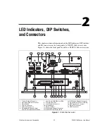
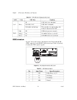
LEDs and DIP Switches
This section contains descriptions of the LED indicators and DIP switches
on the front panel of a NI EVS-1464 series system.
LED Indicators
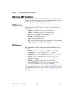
The front panel of a NI EVS-1464 series system features the following
indicators:
•
USER 2
—LabVIEW Real Time programmable LED
•
USER 1
—LabVIEW Real Time programmable LED
•
HDD
—Green when HDD read/write is in progress
•
POWER
—Green when powered on
•
CAM
—Green when powered on
•
ISO
—Orange when an external power supply provides power for the
isolated outputs on the 44-pin D-SUB connector
DIP Switches
The front panel of a NI EVS-1464 series system features the following
switches:
•
RESET
—Recessed reset switch; accessible with a ballpoint pen
•
SAFE MODE
—Runs LabVIEW Real Time in Safe Mode
•
IP RESET
—Resets the LabVIEW Real Time IP address to default
•
NO APP
—Prevents LabVIEW Real Time from running the user
application on startup
•
USER 1
—LabVIEW Real Time-accessible user switch
•
CF MASTER/SLAVE
—Allows the CF slot to be either master
(with no internal HDD) or slave (with internal HDD)
You can modify the behavior of some switches by adjusting BIOS settings.
For more information refer to Chapter 4,
.


