background image

Chapter 3

Signal Connections

NI PCIe-1429 User Manual

3-2

ni.com

MDR 26-Pin Connector

The MDR 26-pin connectors provide reliable high-frequency transfer rates 
between the camera and the image acquisition device. To access these 
connectors, use one MDR 26-pin Camera Link cable for Base 
configuration cameras, and two MDR 26-pin Camera Link cables of the 
same length for Medium or Full configuration cameras. Refer to the 

Cabling

 section for additional information about Camera Link cables, 

including ordering information and cable lengths.

SMB Connector

The SMB connector can be used for front panel trigger connectivity. It can 
be used as a 5V input to trigger acquisitions or as a 5V output to provide 
status information to your system. For further triggering and DIO needs, 
use the NI Camera Link I/O Extension Board. The I/O Extension Board 
provides three differential isolated inputs, three isolated outputs, eight TTL 
inputs/outputs, and quadrature encoder inputs.

Cabling

Use a standard Camera Link cable to connect your camera to the MDR 
26-pin connector on the NI 1429 device. Camera Link cables consist of 
two MDR-26 male plugs linked with a twin-axial shielded cable and are 
available in two shell configurations.

Note

National Instruments recommends purchasing a Camera Link cable. Building your 

own cable is not recommended due to the high-speed signaling on the Camera Link 
interface.

Refer to the 

Specifications of the Camera Link Interface Standard for 

Digital Cameras and Frame Grabbers

 manual for more information about 

Camera Link cables. This manual is available on several Web sites, 
including the Automated Imaging Association Web site at 

www.machinevisiononline.org

.

Summary of Contents for PCIe-1429

Page 1: ...NI Vision NI PCIe 1429 User Manual Base Medium and Full Configuration Camera Link Image Acquisition Device NI PCIe 1429 User Manual July 2006 372015A 01...

Page 2: ...orea 82 02 3451 3400 Lebanon 961 0 1 33 28 28 Malaysia 1800 887710 Mexico 01 800 010 0793 Netherlands 31 0 348 433 466 New Zealand 0800 553 322 Norway 47 0 66 90 76 60 Poland 48 22 3390150 Portugal 35...

Page 3: ...toring in an information retrieval system or translating in whole or in part without the prior written consent of National Instruments Corporation National Instruments respects the intellectual proper...

Page 4: ...t of Communications DOC Changes or modifications not expressly approved by NI could void the user s authority to operate the equipment under the FCC Rules Class A Federal Communications Commission Thi...

Page 5: ...in the software such as menu items and dialog box options Bold text also denotes parameter names italic Italic text denotes variables emphasis a cross reference or an introduction to a key concept It...

Page 6: ...Hardware Overview Functional Overview 2 1 Camera Link and the NI 1429 2 2 Hardware Binarization 2 3 Multiple Tap Data Formatter 2 4 Trigger Control and Mapping Circuitry 2 4 Noise Filtering 2 4 Quadr...

Page 7: ...Contents NI PCIe 1429 User Manual viii ni com Appendix A Technical Support and Professional Services Glossary Index...

Page 8: ...ts are installed with the NI IMAQ driver software Additional camera files are available for download from the National Instruments Industrial Camera Advisor Web site at ni com camera The MDR 26 pin co...

Page 9: ...rmation about Camera Link specifications This manual is available on several Web sites including the Automated Imaging Association site at www machinevisiononline org Overview Developed by a consortiu...

Page 10: ...s and single shot image acquisition memory buffer allocation trigger control and device configuration you can call from the application development environment ADE NI IMAQ handles many of the complex...

Page 11: ...figured inspection to LabVIEW extending the capabilities of the applications if necessary Vision Development Module NI Vision Development Module which consists of NI Vision and NI Vision Assistant is...

Page 12: ...nt can create LabVIEW VIs that perform the prototype you created in Vision Assistant You can then use LabVIEW to add functionality to the generated VI Integration with DAQ and Motion Control Platforms...

Page 13: ...illustrates the key functional components of the NI 1429 Figure 2 1 NI 1429 Block Diagram UART Data Enables Pixel Clock Data Enables Pixel Clock Host Bus Serial Control Serial Control Enables Pixel Cl...

Page 14: ...such as image resolution and the number of bits per pixel and camera control parameters such as frame on demand and exposure control signals These variable parameters are defined on a per camera basi...

Page 15: ...ue range is known as the gray level interval or the threshold interval Binarization works by setting all image pixels that fall within the threshold interval to the image white value and setting all o...

Page 16: ...ine to start an acquisition on a rising edge or a falling edge You also can drive each line asserted or unasserted as a digital I O line You can map pulses from the high speed timing circuitry or the...

Page 17: ...ntrol for cameras has been preprogrammed into the camera file You can use Measurement Automation Explorer MAX to specify the frequency and duration of these signals in easy to use units Acquisition an...

Page 18: ...nterface PCIe Interface The NI 1429 is compliant with PCI Express 1 0a specifications The NI 1429 is intended for a x4 PCIe slot It does not fit properly into a x1 PCIe slot However the NI 1429 does f...

Page 19: ...f a camera file with preprogrammed serial commands does not exist for your camera With clsercon exe you can still communicate serially with your camera From the NI IMAQ bin directory access clsercon e...

Page 20: ...fully supports the recommended serial API described in the Specifications of the Camera Link Interface Standard for Digital Cameras and Frame Grabbers manual This manual is available on several Web s...

Page 21: ...onnector on the NI 1429 This chapter also describes considerations for using the NI 1429 with the NI Camera Link I O Extension Board Connectors The following figure shows the connectors on the NI 1429...

Page 22: ...further triggering and DIO needs use the NI Camera Link I O Extension Board The I O Extension Board provides three differential isolated inputs three isolated outputs eight TTL inputs outputs and qua...

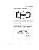
Page 23: ...truments Web site at ni com products Camera Link cables also are available in 1 to 10 m lengths from the 3M Web site at www 3m com Refer to the following figure for 3M part number information Figure 3...

Page 24: ...nstruments Application Engineers make sure every question receives an answer For information about other technical support options in your area visit ni com services or contact your local office at ni...

Page 25: ...om calibration If you searched ni com and could not find the answers you need contact your local office or NI corporate headquarters Phone numbers for our worldwide offices are listed at the front of...

Page 26: ...n signal and a pixel count API Application programming interface area A rectangular portion of an acquisition window or frame that is controlled and defined by software B buffer Temporary storage for...

Page 27: ...transferred to and from computer memory from and to a device or memory on the bus while the processor does something else DMA is the fastest method of transferring data to from computer memory F frame...

Page 28: ...ead is accounted for a x1 link can provide up to 200 MB s of input capability and 200 MB s of output capability Increasing the number of lanes in a link increases maximum throughput by approximately t...

Page 29: ...ge standard utilizing individual differential signal pairs for data transmission in each direction Depending on data transmission rates RS 422 can be used at distances to 4 000 ft 1 275 m RTSI bus Rea...

Page 30: ...an configure each of these lines to start or stop acquisition on a rising or falling edge TTL Transistor transistor logic V VI Virtual Instrument 1 A combination of hardware and or software elements t...

Page 31: ...hardware binarization 2 3 overview 2 1 help technical support A 1 high speed timing 2 5 I instrument drivers NI resources A 1 integration with DAQ and motion control 1 5 K KnowledgeBase A 1 M MDR 26...

Page 32: ...Express interface 2 6 programming examples NI resources A 1 Q quadrature encoder support 2 4 S serial interface 2 7 signal connections 3 1 SMB connector 3 2 software NI resources A 1 overview 1 3 soft...

Reviews: