Appendix A
Specifications
A-2
ni.com
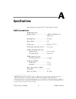
CLKOUT Characteristics
Output frequency
From PXI_CLK10 ...........................10 MHz
From OCXO ....................................10 MHz
From DDS .......................................1 MHz
1
to 80 MHz
Duty cycle...............................................40 to 60%
Output impedance...................................50
Ω
±5%
Output coupling ......................................AC
Amplitude, software configurable to two voltage levels
(low and high drive)
Square wave rise/fall time (10 to 90%)
Low drive.........................................4 ns min,
6 ns max
High drive ........................................4.5 ns min,
7 ns max
Maximum recommended 50
Ω
loads
2
....8, low or high drive, square
or sine
1
The lower limit is load dependent because of the AC coupling. This limit is less than 1 MHz for high-impedance loads.
Open Load
Sine Wave (10 MHz only)
Square Wave
Low Drive
3.6–5.1 V
p-p
4.1–5.4 V
p-p
High Drive
5.4–7.6 V
p-p
7.1–9.2 V
p-p
50
Ω
Load
Sine Wave (10 MHz only)
Square Wave
Low Drive
1.8–2.6 V
p-p
2.0–2.7 V
p-p
High Drive
2.6–3.8 V
p-p
3.5–4.6 V
p-p
2
With an external 50
Ω
splitter. This value does not include cable attenuation or splitter insertion loss.


