background image

Legal Information

Limited Warranty

This document is provided ‘as is’ and is subject to being changed, without notice, in future editions. For the latest version, 

refer to 

ni.com/manuals

. NI reviews this document carefully for technical accuracy; however, NI MAKES NO EXPRESS 

OR IMPLIED WARRANTIES AS TO THE ACCURACY OF THE INFORMATION CONTAINED HEREIN AND 

SHALL NOT BE LIABLE FOR ANY ERRORS.
NI warrants that its hardware products will be free of defects in materials and workmanship that cause the product to fail to 

substantially conform to the applicable NI published specifications for one (1) year from the date of invoice.
For a period of ninety (90) days from the date of invoice, NI warrants that (i) its software products will perform substantially 

in accordance with the applicable documentation provided with the software and (ii) the software media will be free from 

defects in materials and workmanship.
If NI receives notice of a defect or non-conformance during the applicable warranty period, NI will, in its discretion: (i) repair 

or replace the affected product, or (ii) refund the fees paid for the affected product. Repaired or replaced Hardware will be 

warranted for the remainder of the original warranty period or ninety (90) days, whichever is longer. If NI elects to repair or 

replace the product, NI may use new or refurbished parts or products that are equivalent to new in performance and reliability 

and are at least functionally equivalent to the original part or product.
You must obtain an RMA number from NI before returning any product to NI. NI reserves the right to charge a fee for 

examining and testing Hardware not covered by the Limited Warranty.
This Limited Warranty does not apply if the defect of the product resulted from improper or inadequate maintenance, 

installation, repair, or calibration (performed by a party other than NI); unauthorized modification; improper environment; 

use of an improper hardware or software key; improper use or operation outside of the specification for the product; improper 

voltages; accident, abuse, or neglect; or a hazard such as lightning, flood, or other act of nature.
THE REMEDIES SET FORTH ABOVE ARE EXCLUSIVE AND THE CUSTOMER’S SOLE REMEDIES, AND SHALL 

APPLY EVEN IF SUCH REMEDIES FAIL OF THEIR ESSENTIAL PURPOSE.
EXCEPT AS EXPRESSLY SET FORTH HEREIN, PRODUCTS ARE PROVIDED "AS IS" WITHOUT WARRANTY OF 

ANY KIND AND NI DISCLAIMS ALL WARRANTIES, EXPRESSED OR IMPLIED, WITH RESPECT TO THE 

PRODUCTS, INCLUDING ANY IMPLIED WARRANTIES OF MERCHANTABILITY, FITNESS FOR A 

PARTICULAR PURPOSE, TITLE OR NON-INFRINGEMENT, AND ANY WARRANTIES THAT MAY ARISE FROM 

USAGE OF TRADE OR COURSE OF DEALING. NI DOES NOT WARRANT, GUARANTEE, OR MAKE ANY 

REPRESENTATIONS REGARDING THE USE OF OR THE RESULTS OF THE USE OF THE PRODUCTS IN TERMS 

OF CORRECTNESS, ACCURACY, RELIABILITY, OR OTHERWISE. NI DOES NOT WARRANT THAT THE 

OPERATION OF THE PRODUCTS WILL BE UNINTERRUPTED OR ERROR FREE.
In the event that you and NI have a separate signed written agreement with warranty terms covering the products, then the 

warranty terms in the separate agreement shall control.

Copyright

Under the copyright laws, this publication may not be reproduced or transmitted in any form, electronic or mechanical, 

including photocopying, recording, storing in an information retrieval system, or translating, in whole or in part, without the 

prior written consent of National Instruments Corporation.
National Instruments respects the intellectual property of others, and we ask our users to do the same. NI software is protected 

by copyright and other intellectual property laws. Where NI software may be used to reproduce software or other materials 

belonging to others, you may use NI software only to reproduce materials that you may reproduce in accordance with the 

terms of any applicable license or other legal restriction.

End-User License Agreements and Third-Party Legal Notices

You can find end-user license agreements (EULAs) and third-party legal notices in the following locations:

Notices are located in the 

<National Instruments>\_Legal Information

 and 

<National Instruments>


directories.

EULAs are located in the 

<National Instruments>\Shared\MDF\Legal\license

 directory.

Review 

<National Instruments>\_Legal Information.txt

 for information on including legal information in 

installers built with NI products.

U.S. Government Restricted Rights

If you are an agency, department, or other entity of the United States Government (“Government”), the use, duplication, 

reproduction, release, modification, disclosure or transfer of the technical data included in this manual is governed by the 

Restricted Rights provisions under Federal Acquisition Regulation 52.227-14 for civilian agencies and Defense Federal 

Acquisition Regulation Supplement Section 252.227-7014 and 252.227-7015 for military agencies.

Trademarks

Refer to the 

NI Trademarks and Logo Guidelines

 at 

ni.com/trademarks

 for more information on NI trademarks.

ARM, Keil, and µVision are trademarks or registered of ARM Ltd or its subsidiaries.
LEGO, the LEGO logo, WEDO, and MINDSTORMS are trademarks of the LEGO Group.
TETRIX by Pitsco is a trademark of Pitsco, Inc.
FIELDBUS FOUNDATION

 and FOUNDATION

 are trademarks of the Fieldbus Foundation.

EtherCAT

®

 is a registered trademark of and licensed by Beckhoff Automation GmbH.

Artisan Technology Group - Quality Instrumentation ... Guaranteed | (888) 88-SOURCE | www.artisantg.com

Summary of Contents for PXI Express PXIe-1082

Page 1: ...service in house repair center WE BUY USED EQUIPMENT Sell your excess underutilized and idle used equipment We also offer credit for buy backs and trade ins www artisantg com WeBuyEquipment REMOTE IN...

Page 2: ...PXI Express TM NI PXIe 1082 User Manual NI PXIe 1082 User Manual March 2016 372752C 01 Artisan Technology Group Quality Instrumentation Guaranteed 888 88 SOURCE www artisantg com...

Page 3: ...events National Instruments Corporate Headquarters 11500 North Mopac Expressway Austin Texas 78759 3504 USA Tel 512 683 0100 For further support information refer to the NI Services appendix To comme...

Page 4: ...T MAY ARISE FROM USAGE OF TRADE OR COURSE OF DEALING NI DOES NOT WARRANT GUARANTEE OR MAKE ANY REPRESENTATIONS REGARDING THE USE OF OR THE RESULTS OF THE USE OF THE PRODUCTS IN TERMS OF CORRECTNESS AC...

Page 5: ...p or joint venture relationship with NI Patents For patents covering NI products technology refer to the appropriate location Help Patents in your software the patents txt file on your media or the Na...

Page 6: ...e by one or more of the following measures Reorient the antenna of the receiver the device suffering interference Relocate the transmitter the device generating interference with respect to the receiv...

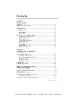
Page 7: ...tion Safety Information 2 1 Chassis Cooling Considerations 2 2 Providing Adequate Clearance 2 2 Chassis Ambient Temperature Definition 2 3 Setting Fan Speed 2 4 Installing Filler Panels 2 4 Installing...

Page 8: ...Resetting the AC Mains Circuit Breaker 3 2 Replacing the Modular Power Supply 3 3 Removal 3 3 Installation 3 3 Configuration 3 4 Connecting Safety Ground 3 4 Connecting to Power Source 3 4 Appendix A...

Page 9: ...ossible damage debris or detached components If damage appears to have been caused during shipment file a claim with the carrier Retain the packing material for possible inspection and or reshipment W...

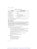
Page 10: ...PXI Express slot dedicated bandwidth x4 PCIe 38 W per slot cooling meets increased PXIe cooling requirements Low jitter internal 10 MHz reference clock for PXI slots with 25 ppm stability Low jitter i...

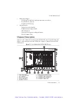
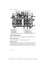
Page 11: ...XIe 1082 chassis front and back panels Figure 1 1 shows the front view of the NI PXIe 1082 Figure 1 2 shows the rear view of the NI PXIe 1082 Figure 1 1 Front View of the NI PXIe 1082 Chassis 1 Power...

Page 12: ...rear rack mount kit differs from the front kit to allow for easier installation into the rack For more information refer to Figure A 3 NI Chassis Rack Mount Kit Components 1 Power Supply Shuttle 2 Pus...

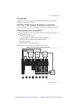
Page 13: ...n a single PXI Express chassis PXI Express compatible products CompactPCI Express compatible 4 Link system controller products CompactPCI Express compatible Type 2 peripheral products PXI peripheral p...

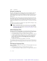
Page 14: ...lation and Configuration for details about the Inhibit Mode switch Hybrid Peripheral Slots The chassis provides four hybrid peripheral slots as defined by the PXI 5 PXI Express Hardware Specification...

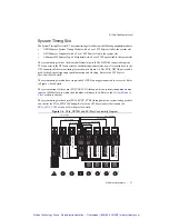
Page 15: ...cking Refer to the PXI Express Specification for details The system timing slot also has a single ended PXI Star trigger connected to every slot Refer to Figure 1 4 for details The system timing slot...

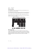
Page 16: ...each adjacent peripheral module to evaluate local bus compatibility Figure 1 5 PXI Trigger Bus Connectivity Diagram PXI Trigger Bus All slots share eight trigger lines You can use these trigger lines...

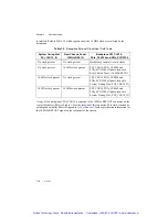
Page 17: ...6 System Reference Clock Default Behavior To synchronize the system to an external clock you can drive PXI_CLK10 from an external source through the PXI_CLK10_IN pin on the System Timing Slot Refer to...

Page 18: ...ternal Clock Input Truth Table System Timing Slot PXI_CLK10_IN Rear Chassis Panel 10 MHz REF IN Backplane PXI_CLK10 PXIe_CLK100 and PXIe_SYNC100 No clock present No clock present Backplane generates i...

Page 19: ...called PXIe_SYNC_CTRL for use when n 1 Refer to Table B 6 XP3 Connector Pinout for the System Timing Slot for system timing slot pinout Refer to Appendix A Specifications for the PXIe_SYNC_CTRL input...

Page 20: ...e protective covers when operating or servicing the chassis Adjustments and service to internal components must be undertaken by qualified service technicians During service of this product the mains...

Page 21: ...uttle The secondary intake and exhaust vents are located along the sides of the chassis Adequate clearance between the chassis and surrounding equipment or blockages must be maintained to ensure prope...

Page 22: ...the user s responsibility to ensure that this ambient temperature does not exceed the rated ambient temperature as stated in Appendix A Specifications If the temperature exceeds the stated spec the po...

Page 23: ...er to Figure A 3 NI Chassis Rack Mount Kit Components Note You may want to remove the feet from the NI PXIe 1082 chassis when rack mounting To do so remove the screws holding the feet in place Connect...

Page 24: ...on contains general installation instructions for installing a PXI Express system controller in a NI PXIe 1082 chassis Refer to your PXI Express system controller user manual for specific instructions...

Page 25: ...screws 5 Connect the keyboard mouse and monitor to the appropriate connectors Connect devices to ports as required by your system configuration 6 Power on the chassis Verify that the system controller...

Page 26: ...amage to the chassis ensure that the peripheral module is being installed into a slot designed to accept it Refer to Chapter 1 Getting Started for a description of the various slot types This section...

Page 27: ...ssis making sure that the injector ejector handle is pushed down as shown in Figure 2 5 5 When you begin to feel resistance push up on the injector ejector handle to fully seat the module into the cha...

Page 28: ...mperature has exceeded the chassis operating range If the inhibit switch LED is flashing red the power supply outputs are not within voltage regulation requirements If the inhibit switch LED is steady...

Page 29: ...Referring to Table 2 2 connect one lead of the voltmeter to a supply pin on the remote voltage monitoring connector 9 pin D SUB on the rear panel Refer to Table 2 1 for a pinout diagram of the remote...

Page 30: ...wer off the chassis To remotely power off the chassis connect the Inhibit pin pin 5 to a Logic Ground pin pin 1 or 9 As long as this connection exists the chassis will remain off standby when you remo...

Page 31: ...geBase 3TJDOND8 at ni com support The configuration steps for single or multiple chassis systems are the same Figure 2 6 Multichassis Configuration in MAX PXI 1 System Configuration 1 Launch MAX 2 In...

Page 32: ...ss specification allows many combinations of PXI Express chassis and system modules To assist system integrators the manufacturers of PXI Express chassis and system modules must document the capabilit...

Page 33: ...ument included with your kit before attempting any procedures in this chapter Caution Many components within the chassis are susceptible to static discharge damage Service the chassis only in a static...

Page 34: ...You can easily remove the chassis air filters from the rear of the chassis by removing the filter retainer To remove the filter retainer loosen the retainer screw The filter cover and retainer are sho...

Page 35: ...may damage your chassis and the power supply shuttle Before connecting the power supply shuttle to a power source read this section and the Read Me First Safety and Electromagnetic Compatibility docu...

Page 36: ...cooling performance recommended or Auto for quieter operation Set the Inhibit Mode switch to the Default position Connecting Safety Ground Refer to the Connecting Safety Ground section of Chapter 2 I...

Page 37: ...current protection 10 A circuit breaker Line regulation 3 3 V 0 2 5 V 0 1 12 V 0 1 Efficiency 70 typical Power disconnect The AC power cable provides main power disconnect The front panel power switc...

Page 38: ...ould not exceed 140 W The maximum power dissipated in a peripheral slot should not exceed 38 25 W Voltage Maximum Current 3 3 V 32 A 5 V 27 A 12 V 32 A 12 V 2 0 A 5 VAUX 2 0 A Slot 5 V V I O 3 3 V 12...

Page 39: ...surization through two 110 cfm fans with High Auto speed selector Slot airflow direction Bottom of module to top of module Module cooling intake Bottom rear of chassis Module cooling exhaust Along bot...

Page 40: ...ironment Ambient temperature range 40 to 71 C Tested in accordance with IEC 60068 2 1 and IEC 60068 2 2 Meets MIL PRF 28800F Class 3 limits Relative humidity range 5 to 95 noncondensing Tested in acco...

Page 41: ...and other safety certifications refer to the product label or the Online Product Certification section Electromagnetic Compatibility This product meets the requirements of the following EMC standards...

Page 42: ...Environmental Impact web page at ni com environment This page contains the environmental regulations and directives with which NI complies as well as other environmental information not included in t...

Page 43: ...gnal swing 3 3 V 0 3 V Note For other specifications refer to the PXI 1 Hardware Specification 100 MHz System Reference Clock PXIe_CLK100 and PXIe SYNC100 Maximum slot to slot skew 100 ps Accuracy 25...

Page 44: ...square wave or sine wave System timing slot PXI_CLK10_IN 5 V or 3 3 V TTL signal Rear panel BNC input impedance 50 5 Maximum jitter introducedby backplane 1 ps RMS phase jitter 10 Hz to1 MHz range PXI...

Page 45: ...ions Standard chassis Height 6 97 in 177 1 mm Width 10 68 in 271 4 mm Depth 15 61 in 396 5 mm Note 0 57 in 14 5 mm is added to height when feet are installed When tilted with front feet extended on ta...

Page 46: ...e front of the instrument cabinet Notice that the front and rear chassis mounting holes size M4 are symmetrical Figure A 1 NI PXIe 1082 Chassis Dimensions Front and Side 10 68 in 271 4 mm 15 61 in 396...

Page 47: ...Ie 1082 User Manual Figure A 2 NI PXIe 1082 Chassis Dimensions Bottom 12 700 in 322 58 mm 1 01 in 25 7 mm 1 02 in 25 8 mm 8 650 in 219 7 mm Artisan Technology Group Quality Instrumentation Guaranteed...

Page 48: ...ssis Rack Mount Kit Components Note The chassis shown in Figure A 3 is representative of the NI PXI 1042 NI PXIe 1062Q NI PXIe 1082 product lines 1 Front Rack Mount Kit 2 NI Chassis 3 Optional Rear Ra...

Page 49: ...Pinout for the System Timing slot Table B 7 shows the XP4 Connector Pinout for the System Timing slot Table B 8 shows the P1 Connector Pinout for the Hybrid peripheral slots Table B 9 shows the XP3 Co...

Page 50: ...4PETn1 GND 4 4PETp2 4PETn2 GND 4PERp2 4PERn2 GND 4PERp1 4PERn1 GND 5 4PETp3 4PETn3 GND 4PERp3 4PERn3 GND RSV RSV GND 6 RSV RSV GND RSV RSV GND RSV RSV GND 7 RSV RSV GND RSV RSV GND RSV RSV GND 8 RSV...

Page 51: ...1PERp3 1PERn3 GND 2PETp0 2PETn0 GND 8 2PETp1 2PETn1 GND 2PERp1 2PERn1 GND 2PERp0 2PERn0 GND 9 2PETp2 2PETn2 GND 2PERp2 2PERn2 GND 2PETp3 2PETn3 GND 10 3PETp0 3PETn0 GND 3PERp0 3PERn0 GND 2PERp3 2PERn3...

Page 52: ...DS TARB1 PXIe_DS TARB1 GND PXI_ STAR0 PXI_ STAR1 GND PXIe_DS TARB9 PXIe_DS TARB9 GND 5 PXIe_DS TARA1 PXIe_DS TARA1 GND PXI_ STAR2 PXI_ STAR3 GND PXIe_DS TARC10 PXIe_DS TARC10 GND 6 PXIe_DS TARC2 PXIe_...

Page 53: ...ETp3 1PETn3 GND 1PERp3 1PERn3 GND 1PETp4 1PETn4 GND 8 1PETp5 1PETn5 GND 1PERp5 1PERn5 GND 1PERp4 1PERn4 GND 9 1PETp6 1PETn6 GND 1PERp6 1PERn6 GND 1PETp7 1PETn7 GND 10 RSV RSV GND RSV RSV GND 1PERp7 1P...

Page 54: ...IPMB_SCL IPMB_SDA GND PERR GND 16 GND DEVSEL GND V I O STOP LOCK GND 15 GND 3 3V FRAME IRDY BD_SEL TRDY GND 12 to 14 Key Area 11 GND AD 18 AD 17 AD 16 GND C BE 2 GND 10 GND AD 21 GND 3 3V AD 20 AD 19...

Page 55: ...GND 7 1PETp3 1PETn3 GND 1PERp3 1PERn3 GND 1PETp4 1PETn4 GND 8 1PETp5 1PETn5 GND 1PERp5 1PERn5 GND 1PERp4 1PERn4 GND 9 1PETp6 1PETn6 GND 1PERp6 1PERn6 GND 1PETp7 1PETn7 GND 10 RSV RSV GND RSV RSV GND 1...

Page 56: ...rements and provides warranty sparing and calibration services to help you maintain accuracy and minimize downtime over the life of your system Visit ni com services for more information Warranty and...

Page 57: ...tted online receives an answer Software Support Service Membership The Standard Service Program SSP is a renewable one year subscription included with almost every NI software product including NI Dev...

Page 58: ...a 106 G giga 109 T tera 1012 Symbols Degrees Equal or greater than Equal or less than Percent A A Amperes AC Alternating current ANSI American National Standards Institute Auto Automatic fan speed con...

Page 59: ...I It uses industry standard mechanical components and high performance connector technologies to provide an optimized system intended for rugged applications It is electrically compatible with the PCI...

Page 60: ...g 1 grams 2 a measure of acceleration equal to 9 8 m s2 GPIB General Purpose Interface Bus IEEE 488 gRMS A measure of random vibration The root mean square of acceleration levels in a random vibratio...

Page 61: ...ll change as a result of a specified change in input AC voltage step change from 90 to 132 VAC or 180 to 264 VAC load regulation The maximum steady state percentage that a DC voltage output will chang...

Page 62: ...ssembly installed into an empty slot to improve the airflow in adjacent slots standby The backplane is unpowered off but the chassis is still connected to AC power mains System controller A module con...

Page 63: ...z REF IN and OUT BNC connectors on the rear of the chassis can be used to synchronize multiple chassis to one reference clock The PXI backplane specification defines implementation guidelines for PXI_...

Page 64: ...ing of PXIe 1082 chassis 2 2 filler panel installation 2 4 setting fan speed 2 4 slot blocker installation 2 4 D DB 9 connector pinout table 2 10 power supply voltages table 2 11 E electromagnetic com...

Page 65: ...6 PXI local bus routing 1 8 PXIe_SYNC_CTRL 1 11 specifications A 6 system controller slot 1 6 system reference clock 1 9 system timing slot 1 7 trigger bus 1 8 O optional equipment 1 4 P pinouts B 1 D...

Page 66: ...onmental operating environment A 4 storage environment A 4 external clock source A 8 mechanical A 9 PXI differential star triggers PXIe DSTARA PXIe DSTARB PXIe DSTARC A 9 PXI star trigger A 8 PXIe_SYN...

Page 67: ...service in house repair center WE BUY USED EQUIPMENT Sell your excess underutilized and idle used equipment We also offer credit for buy backs and trade ins www artisantg com WeBuyEquipment REMOTE IN...

Reviews: