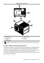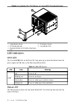
Figure 11. Installing PXI, PXI Express, or CompactPCI Peripheral Modules
3
2
1
4
5
PXIe-1
083
1. Injector/Ejector Handle
2. PXI Peripheral Module
3. Peripheral Module Front Panel Mounting Screws
(2x)
4. PXI Express Chassis
5. Injector/Ejector Rail
LED Indicators
LINK LED
The tri-color
LINK
LED on the PXIe-1083 front panel gives status information about the
power supply and link state, as the following table describes.
Table 5. LINK LED Colors
LED
Color
Meaning
LINK
Off
Power is off.
Blinking red
Power is out of spec.
Solid amber
Power is within spec; no link to chassis.
Solid green
Power is within spec; link established.
Status LED
The following figure shows the front panel Status LED. The following table describes the
Status LED states.
18
|
ni.com
|
PXIe-1083 User Guide

