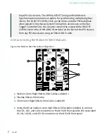
Figure 4. NI 5665 3.6 GHz VSA Slave Module Cable Configuration
NI PXIe-5653
Synthesizer
REF IN
10 MHz
5 V p-p MAX
REF OUT
10 MHz
1.5 V p-p MAX
REF OUT
100 MHz
1.5 V p-p MAX
LO3
800 MHz
LO2
4 GHz
LO1
3.2 GHz - 8.3 GHz
ESD
SENSITIVE
OUT
ALL PORTS
50
Ω
ACCESS
ACTIVE
CLKIN
CLKOUT
PFI 1
ESD
SENSITIVE
TT L
6.3 Vp-p
MAX
2 Vp-p
NOM
+20 dBm MAX
50
Ω
50
Ω
50
Ω
NI PXIe-5622
16-Bit IF Digitizer
IF IN
ESD
SENSITIVE
ACCESS
ACTIVE
ALL PORTS
50
Ω
ACCESS
ACTIVE
CLKIN
CLKOUT
PFI 1
ESD
SENSITIVE
TT L
6.3 Vp-p
MAX
2 Vp-p
NOM
+20 dBm MAX
50
Ω
50
Ω
50
Ω
NI PXIe-5622
16-Bit IF Digitizer
IF IN
ESD
SENSITIVE
ACCESS
ACTIVE
ALL PORTS
50
Ω
K
K
K
K
J
J
J
J
J
J
M
M
M
M
M
M
NI PXIe-5603
Downconverter 20 Hz - 3.6 GHz
NI PXIe-5603
Downconverter 20 Hz - 3.6 GHz
2
1
3
1. Short, Semi-Rigid SMA-to-SMA Cable, Labeled K
2. Flexible SMA-to-SMA Cable
3. Medium, Semi-Rigid SMA-to-SMA Cables, Labeled M
1. Using the short, semi-rigid SMA-to-SMA cable (labeled K), connect the IF OUT
connector on the slave NI 5603 front panel to the IF IN connector on the slave
NI 5622 front panel.
2. Using the flexible SMA-to-SMA cable, connect the CLK OUT connector from the
preceding NI 5622 front panel to the CLK IN connector on the next NI 5622
front panel. This cable passes the 100 MHz Reference Clock from the
preceding NI 5622 to the CLK IN connector of the next NI 5622.
3. Using the three medium, semi-rigid SMA-to-SMA cables (labeled M), connect
the LO1 OUT, LO2 OUT, and LO3 OUT connectors on the preceding NI 5603
front panel to the associated LO1 IN, LO2 IN, and LO3 IN connectors on the
next NI 5603 front panel.
4. Hand-tighten all SMA cable ends on the SMA connectors after the cable center
pins are correctly aligned and connected. The cable connectors should tighten
without much torque or effort. If a cable bends due to incorrect alignment,
remove the cable from the front panel connector and reconnect the cable
center pin on the SMA cable to the SMA connector.
ni.com
8
PXIe-5665 3.6 GHz Getting Started


