background image

Appendix B

5B Series Module Data Sheets

SC-2311 User Manual

B-48

ni.com

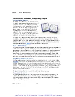
Signal isolation by transformer coupling uses a proprietary modulation technique for linear,
stable and reliable performance. The differential input circuit on the field side is fully
floating, eliminating the need for any input grounding. A demodulator on the computer side
of the signal transformer recovers the original signal, which is then filtered and buffered to
provide a low-noise, low-impedance output signal. The output common must be kept within
±3 V of power common.

Convenience Features

A series output switch eliminates the need for external multiplexing in many applications.
The switch is turned on by an active-low enable input. The enable input should be grounded
to power common if the output need not be switched, as on the 5B01 and 5B08

backplanes

.

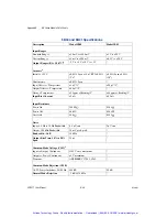
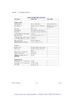
Figure 1. 5B47 Functional Block Diagram

Input Types

Thermocouple Types:
J, K, T, E, R, S, B

Output Ranges

0 to +5 V
(+1 V to +5 V - custom)

Figure 2. 5B47 Input Field Connections

Artisan Technology Group - Quality Instrumentation ... Guaranteed | (888) 88-SOURCE | www.artisantg.com

Summary of Contents for SC-2311

Page 1: ...l service in house repair center WE BUY USED EQUIPMENT Sell your excess underutilized and idle used equipment We also offer credit for buy backs and trade ins www artisantg com WeBuyEquipment REMOTE INSPECTION Remotely inspect equipment before purchasing with our interactive website at www instraview com LOOKING FOR MORE INFORMATION Visit us on the web at www artisantg com for more information on ...

Page 2: ...ning SC 2311 User Manual Connectivity for 5B and SSR Modules SC 2311 User Manual February 2001 Edition Part Number 322906A 01 Artisan Technology Group Quality Instrumentation Guaranteed 888 88 SOURCE www artisantg com ...

Page 3: ...4 24 Germany 089 741 31 30 Greece 30 1 42 96 427 Hong Kong 2645 3186 India 91805275406 Israel 03 6120092 Italy 02 413091 Japan 03 5472 2970 Korea 02 596 7456 Mexico 5 280 7625 Netherlands 0348 433466 New Zealand 09 914 0488 Norway 32 27 73 00 Poland 0 22 528 94 06 Portugal 351 1 726 9011 Singapore 2265886 Spain 91 640 0085 Sweden 08 587 895 00 Switzerland 056 200 51 51 Taiwan 02 2528 7227 United K...

Page 4: ...ilures caused by owner s failure to follow the National Instruments installation operation or maintenance instructions owner s modification of the product owner s abuse misuse or negligent acts and power failure or surges fire flood accident actions of third parties or other events outside reasonable control Copyright Under the copyright laws this publication may not be reproduced or transmitted i...

Page 5: ...xt denotes variables emphasis a cross reference or an introduction to a key concept This font also denotes text that is a placeholder for a word or value that you must supply monospace Text in this font denotes text or characters that you should enter from the keyboard sections of code programming examples and syntax examples This font is also used for the proper names of disk drives paths directo...

Page 6: ...SC 2311 2 9 Chapter 3 5B Series Modules Overview 3 1 5B30 5B31 5B40 5B41 Voltage Input Module 3 2 5B32 Process Current Input Module 3 2 5B34 RTD Input Isolated 2 or 3 Wire RTD Module 3 2 5B35 RTD Input Isolated 4 Wire RTD Module 3 3 5B36 Potentiometer Input Module 3 3 5B37 Thermocouple Input Module with Cold Junction Compensation 3 3 5B38 Strain Gauge Input Module 3 4 5B42 Process Current Input Mo...

Page 7: ...put Modules 4 3 SSR OAC 5 120 VAC 4 4 SSR OAC 5A 240 VAC 4 5 SSR ODC 5 3 60 DVC 4 5 Appendix A Specifications Appendix B 5B Series Module Data Sheets Appendix C Power Requirements for the SC 2311 with 5B and SSR Series Modules Appendix D Technical Support Resources Glossary Index Artisan Technology Group Quality Instrumentation Guaranteed 888 88 SOURCE www artisantg com ...

Page 8: ...2 5 Installing an I O Panelette Label 2 9 Figure 2 6 Rack Mount Option 2 10 Figure 2 7 Stack Mount Option 2 11 Figure 4 1 SSR IAC AC Input Diagram 4 2 Figure 4 2 SSR IDC DC Input Diagram 4 3 Figure 4 3 SSR OAC AC Output Diagram 4 4 Figure 4 4 SSR ODC DC Output Diagram 4 6 Tables Table C 1 5B Series Current Requirements C 1 Table C 2 SSR Series Current Requirements C 2 Artisan Technology Group Qual...

Page 9: ...rocess current input modules 5B34 RTD input isolated 2 or 3 wire RTD modules 5B35 RTD input isolated 4 wire RTD modules 5B36 potentiometer input modules 5B37 thermocouple input with cold junction compensation modules 5B42 process current input with regulated 20 VDC loop modules 5B47 linearized thermocouple input with cold junction compensation modules 5B38 strain gauge input modules 5B45 46 freque...

Page 10: ...r connecting to the 5B Series modules as well as the SSR Series modules The SC 2311 allows you to optimize connectivity to the terminal blocks through the use of panelettes The SC 2311 shielded carrier has a portable enclosure and is ideal for laptop and desktop applications The 5B Series modules along with the SC 2311 provide a high performance inexpensive means of analog signal conditioning You ...

Page 11: ...2 5B34 5B35 5B36 5B37 5B38 5B40 41 5B42 5B45 46 5B47 Up to eight of the following SSR Series modules for digital signal conditioning SSR IAC 5 SSR IAC 5A SSR IDC 5 SSR OAC 5 SSR OAC 5A SSR ODC 5 SC 2311 User Manual External power supply supplied 68 pin E Series DAQ device documentation and 68 pin E Series cable Flathead screwdriver 0 1 in supplied Number 1 and 2 Phillips head screwdrivers Artisan ...

Page 12: ... avoid such damage when you handle the products take the following precautions Ground yourself by using a grounding strap or by touching a grounded object Touch the antistatic package to a metal part of your computer chassis before removing the modules from the packaging Caution Never touch the exposed pins of connectors Remove the modules from the packaging and inspect the modules for any sign of...

Page 13: ...essories Configuring the SC 2311 The SC 2311 contains the following slide switches that are used to configure the device SW5 SW4 SW3 SW2 You must configure these slide switches prior to operating the SC 2311 To access the slide switches remove the eight top cover screws and the top cover as shown in Figure 2 1 See Figure 2 2 for switch locations Artisan Technology Group Quality Instrumentation Gua...

Page 14: ...etting Up the SC 2311 SC 2311 User Manual 2 2 ni com Figure 2 1 SC 2311 Top Cover Removal 1 Top Cover Screws 2 Top Cover 3 SC 2311 3 2 1 Artisan Technology Group Quality Instrumentation Guaranteed 888 88 SOURCE www artisantg com ...

Page 15: ...nts Corporation 2 3 SC 2311 User Manual Figure 2 2 SC 2311 Parts Locator Diagram 1 SW5 2 SW4 3 SW3 4 5B Series Modules 5 SSR Series Modules 6 SW2 7 Safety Ground 6 3 2 1 4 5 7 Artisan Technology Group Quality Instrumentation Guaranteed 888 88 SOURCE www artisantg com ...

Page 16: ...tting if you are not using 5B modules to take measurements Setting SW4 Setting SW4 to the SPLY GND AIGND SHORT position allows the 5B Series modules to function properly when using the external power supply This switch setting short circuits the external supply ground to the AIGND of the E Series DAQ device In most cases SW4 should remain in the SPLY GND AIGND SHORT position Setting SW3 Setting SW...

Page 17: ...y from the E Series DAQ device Note The maximum current that the DAQ device can deliver depends on which DAQ device you have selected When using the Board 5V SSR setting it is necessary to know the current requirements of the SSR Series modules and the current available from the DAQ device you are using Safety Information Cautions Do not operate the device in an explosive atmosphere or where there...

Page 18: ...ing or disconnecting signal lines to the SC 2311 screw terminals make sure the lines are powered off Potential differences between the lines and the SC 2311 ground can create a shock hazard while you connect the lines Connections including power signals to ground and vice versa that exceed any of the maximum signal ratings on the SC 2311 device can create a shock or fire hazard or can damage any o...

Page 19: ...ge numbers of wires directly to your internal accessory You can machine the blank I O panelettes to make custom I O panelettes to suit your application Use the preconfigured I O panelettes to quickly connect and disconnect standard connectors Note For RF emission compliance you cannot use BNC panelettes Refer to Figure 2 4 and use the following steps to install any of the I O panelettes 1 Choose o...

Page 20: ...two labels on single width I O panelettes and three or more labels on wider panelettes Caution Do not use a panelette for signals that exceed the panelette rating 1 Thermocouple I O Panelette 2 M2 5 6 Screw 3 BNC I O Panelette 4 Strain Relief I O Panelette 5 D Sub I O Panelette 6 Dual D Sub I O Panelette 7 Blank I O Panelette 1 2 3 5 6 N A T I O N A L I N S T R U M E N T S S C 2 3 1 1 S i g n a l ...

Page 21: ...it Refer to Figure 2 6 and use the following steps to install the rack mount kit on your SC 2311 enclosure 1 Attach a rack mount bracket to one side of the enclosure with four 4 40 1 4 in screws from the rack mount kit 2 Attach a rack mount bracket to the other side of the enclosure with four 4 40 1 4 in screws from the rack mount kit Note You must remove the rubber feet from the bottom of the SC ...

Page 22: ...enclosure on top of the lower enclosure 3 Attach the stack mount brackets to both ends of the upper enclosure with the 4 40 1 4 in flathead screws from the stack mount kit Note You must remove the rubber feet from all but the bottom enclosure before stacking the enclosures 1 4 40 x 1 4 in Screws 2 Rack Mount Brackets 2 N A T I O N A L I N S T R U M E N T S SC 2311 S i g n a l C o n d i t i o n i n...

Page 23: ...nt kits You can remove the stack mount kit handles if necessary by removing the two screws that attach the handle Note You can also use the stack mounting brackets as handles 1 4 40 1 4 in Flathead Screws 2 Stack Mount Brackets 1 NATIONAL INSTRUMENTS SC 2311 Signal Conditioning with Configurable Connectors 1 2 Artisan Technology Group Quality Instrumentation Guaranteed 888 88 SOURCE www artisantg ...

Page 24: ...11 to connect to your I O signals Connect the panelettes to the input terminal blocks of corresponding 5B channels After the signals are conditioned they are routed through a shielded 68 position cable to an E Series DAQ device for measurement The 5B Series modules include the following 5B30 5B31 5B40 5B41 voltage input modules 5B32 process current input modules 5B34 RTD input isolated 2 or 3 wire...

Page 25: ...ignal This measurement is accomplished by reading the voltage across a precision 20 Ω resistor that is included with the 5B32 module These modules scale the input current to a 0 5 V output signal that is routed from the SC 2311 to the E Series DAQ device for measurement You can insert and use the 5B32 process current input modules in any of the eight 5B channels inside the SC 2311 5B34 RTD Input I...

Page 26: ...2311 to the E Series DAQ device for measurement You can insert and use the 5B36 potentiometer input modules in any of the eight 5B channels inside the SC 2311 5B37 Thermocouple Input Module with Cold Junction Compensation The 5B37 thermocouple input module is capable of accepting input signals from J K T E R S and B type thermocouples The 5B37 also uses cold junction compensation circuitry which i...

Page 27: ...lated 20 V supply for current measurement The module filters and amplifies the 4 20 mA process current input to produce an accurately scaled low noise low impedance output of 1 to 5 V or 2 to 10 V You can insert and use the 5B42 process current input modules in any of the eight 5B channels inside the SC 2311 5B45 46 Frequency Input Module The 5B45 frequency input modules accept full scale frequenc...

Page 28: ...ompensation circuitry which is part of the SC 2311 accessory to compensate for the parasitic thermocouples formed at the input screw terminals of the SC 2311 The 5B47 linearly scales the thermocouples temperature into a 0 5 V signal that is routed form the SC 2311 to the E Series DAQ device for measurement You can insert and use the 5B47 linearized thermocouple input modules in any of the eight 5B...

Page 29: ...0 VAC SSR IAC 5A 240 VAC SSR IDC 5 3 to 32 VDC Output modules SSR OAC 5 120 VAC SSR OAC 5A 240 VAC SSR ODC 5 3 to 60 VDC See Appendix C Power Requirements for the SC 2311 with 5B and SSR Series Modules to find the power requirements for your SSR Series modules Input Modules Input SSR Series modules sense voltages from a field source and return a logic value to the E Series DAQ device If a voltage ...

Page 30: ... IAC 5 in any of the eight SSR sockets inside the SC 2311 SSR IAC 5A 240 VAC The SSR IAC 5A input module senses 180 280 VAC DC from a field source and converts it into a TTL logic signal When a signal in this voltage range is detected at its input the SSR generates a logic low signal on the corresponding DIO line of the E Series DAQ device Otherwise the SSR returns a logic high signal Figure 4 1 s...

Page 31: ... inside the SC 2311 Output Modules SSR Series output modules use DIO lines on an E Series DAQ device to control external devices If a DIO line sends a logic low signal the output module turns on and current flows If the DIO line sends a logic high signal the output module turns off SSR Series output modules are similar to conventional relays but there are some important differences Unlike conventi...

Page 32: ...ey do not turn off completely A small leakage current flows all the time even in the off state For most control applications this current causes no problems SSR OAC 5 120 VAC The SSR OAC 5 output module uses a DIO line from the E Series DAQ device to switch an external 24 140 VAC load at up to 3 5 A When the E Series DAQ device DIO line sends a logic low this turns on the corresponding SSR OAC 5 m...

Page 33: ...e E Series DAQ device DIO line sends a logic low this turns on the corresponding SSR OAC 5A module and allows current to flow If a logic high is sent the module turns off You can insert and use the SSR OAC 5A in any of the eight SSR sockets inside the SC 2311 SSR ODC 5 3 60 DVC The SSR ODC 5 output module uses a DIO line from the E Series DAQ device to switch an external 3 60 VDC load at up to 3 A...

Page 34: ...ODC DC Output Diagram You can insert and use the SSR ODC 5 in any of the eight SSR sockets inside the SC 2311 1 2 3 4 Rx VDC DC Control Voltage Spike Protection Load Driver Circuit Load Artisan Technology Group Quality Instrumentation Guaranteed 888 88 SOURCE www artisantg com ...

Page 35: ... or 16 unconditioned single ended inputs Input characteristics See Appendix B 5B Series Module Data Sheets Digital I O Number of channels 8 SSR Series modules or 8 unconditioned DIO lines I O characteristics See the SSR Series section in this appendix Physical Dimensions 30 7 by 25 4 by 8 6 cm 12 1 by 10 by 3 4 in Weight without modules or panelettes 2 0 kg 4 3 pounds Artisan Technology Group Qual...

Page 36: ... Electrical immunity Evaluated to EN 61326 1 1997 A1 1998 Table 1 Safety EN 61010 1 Note For full EMC and EMI compliance you must operate this device with shielded cabling See the Declaration of Conformity DoC for this product for any additional regulatory compliance information To obtain the DoC for this product click Declaration of Conformity at http www ni com hardref nsf This website lists the...

Page 37: ...y II SSR Series input module characteristics Characteristic SSR IDC 5 SSR IAC 5 SSR IAC 5A Nominal input 5 VDC 120 VAC 240 VAC Voltage range 3 32 VDC 90 140 VAC 180 280 VAC Voltage level ON state min OFF state min 3 VDC 1 VDC 90 VAC 25 VAC 180 VAC 50 VAC Supply current 10 mA 10 mA 10 mA Input impedance 1 8 kΩ 22 kΩ 60 kΩ Delay time Turn on max Turn off max 0 20 mS 0 40 mS 20 mS 20 mS 20 mS 20 mS A...

Page 38: ... 55 C 2 0 A at 25 C 1 6 A at 40 C 1 1 A at 55 C 2 0 A at 25 C 1 6 A at 40 C 1 1 A at 55 C Current rating four modules populated 2 75 A at 25 C 2 35 A at 40 C 2 0 A at 55 C 1 7 A at 25 C 1 3 A at 40 C 0 9 A at 55 C 1 7 A at 25 C 1 3 A at 40 C 0 9 A at 55 C Current rating eight modules populated 2 1 A at 25 C 1 75 A at 40 C 0 8 A at 55 C 1 2 A at 25 C 0 8 A at 40 C 0 6 A at 55 C 1 2 A at 25 C 0 8 A ...

Page 39: ... 5B Series modules data sheets included are the following 5B30 5B31 5B32 5B34 5B35 5B36 5B37 5B38 5B40 5B41 5B42 5B45 5B46 5B47 1 Copyright Analog Devices Inc 1995 2000 Reprinted with permission of the copyright owner All rights reserved Analog Devices Inc from Analog Devices Web Site www analog com Artisan Technology Group Quality Instrumentation Guaranteed 888 88 SOURCE www artisantg com ...

Page 40: ...scale input voltage is subtracted from the input signal to set the zero scale value For user convenience the zero can be optionally factory set to meet custom needs This allows suppression of a zero scale input value many times larger Internal multi pole lowpass filtering with a four Hz cutoff 3dB enhances normal mode noise on signal and common mode noise on signal return rejection at 50 60 Hz ena...

Page 41: ...ive low enable input The enable input should be grounded to power common if the output need not be switched Figure 1 5B30 and 5B31 Functional Block Diagram Input Ranges 5B30 mV Input 10 to 100 mV 5 to 500 mV custom 5B31 V Input 1 to 20 V 0 5 to 20 V custom Output Ranges 5B30 5B31 5 V to 5 V or 0 to 5 V Figure 2 5B30 and 5B31 Input Field Connections Artisan Technology Group Quality Instrumentation ...

Page 42: ...ture 25 ppm of Reading C 50 ppm of Reading C Input Bias Current 3 nA 0 2 nA Input Resistance Power On 5 M 650 k Power Off 40 k 650 k Overload 40 k 650 k Noise Input 0 1 Hz to 10 Hz Bandwidth 0 2 µV rms 2 µV rms Output 100 kHz Bandwidth 200 µV rms Bandwidth 3 dB 4 Hz Output Rise Time 10 to 90 Span 200 ms Common Mode Voltage CMV 3 Input to Output Continuous 1500 V rms maximum Output to Power Continu...

Page 43: ...mm x 15 1 mm Environmental Temperature Range Rated Performance 25 C to 85 C Operating 40 C to 85 C Storage 40 C to 85 C Relative Humidity 0 to 93 40 C noncondensing RFI Susceptibility 0 5 Span error 400 MHz 5 Watt 3 ft Specifications same as model 5B30 1 Vz is the nominal input voltage that results in a 0 V output 2 Includes the combined effects of repeatability hysteresis and nonlinearity and ass...

Page 44: ...le gain At the amplifier input a stable laser trimmed zero scale input offset is subtracted from the input signal to set the zero scale value for the 4 20 mA range For user convenience the zero can be optionally factory set to meet custom needs This allows suppression of a zero scale input value many times larger than the total span for precise expanded scale measurements Internal multi pole lowpa...

Page 45: ...itch is turned on by an active low enable input If the switch is to be on at all times the enable input should be grounded to power common as it is on the 5B01 and 5B08 backplanes Figure 1 5B32 Functional Block Diagram Input Ranges 4 mA to 20 mA Output Ranges 0 to 5 V 5 V to 5 V custom Figure 2 5B32 Input Field Connections Artisan Technology Group Quality Instrumentation Guaranteed 888 88 SOURCE w...

Page 46: ...erature 20 µV C Gain vs Temperature 0 0025 of Reading C Input Resistor5 Value 20 0 Accuracy 0 1 Stability vs Temperature 0 001 C Noise Input 0 1 Hz to 10 Hz Bandwidth 10 nA rms Output 100 kHz Bandwidth 200 µV rms Bandwidth 3 dB 4 Hz Output Rise Time 10 to 90 Span 200 ms Common Mode Voltage CMV 3 Input to Output Continuous 1500 V rms maximum Output to Power Continuous 3 V maximum Transient ANSI IEE...

Page 47: ... MHz 5 Watt 3 ft 1Iz is the nominal input current that results in a 0 V output 2Includes the combined effects of repeatability hysteresis and nonlinearity and assumes RL 50 k Does not include current to voltage input resistor AC1362 error 3The output common must be kept within 3 V of power common 4Loads heavier than 50 k will degrade nonlinearity and gain temperature coefficient 5The current to vo...

Page 48: ...er input and module output to zero volts at that scale point The current sources and the amplifier input are protected to withstand input overvoltage up to 240 V rms A differential chopper stabilized input amplifier provides stable gain and exceptionally low drift This allows the use of very low RTD excitation current to minimize self heating and preserve measurement accuracy Along with module gai...

Page 49: ...s turned on by an active low enable input If the switch is to be on at all times the enable input should be grounded to power common as it is on the 5B01 and 5B08 backplanes Figure 1 5B34 Functional Block Diagram Input Types 100 Platinum RTD 10 Copper RTD 120 Nickel RTD Output Range 0 to 5 V Figure 2 5B34 Input Field Connections Artisan Technology Group Quality Instrumentation Guaranteed 888 88 SO...

Page 50: ...ut Offset vs Temperature 20 µV C Gain vs Temperature 0 005 of Reading C Input Bias Current 3 nA Input Resistance Power On 5 M Power Off 40 k Overload 40 k Noise Input 0 1 Hz to 10 Hz Bandwidth 0 2 µV rms Output 100 kHz Bandwidth 200 µV rms Bandwidth 3 dB 4 Hz Output Rise Time 10 to 90 Span 200 ms Common Mode Voltage CMV Input to Output Continuous 1500 V rms maximum Output to Power Continuous4 3 V ...

Page 51: ...tput Resistance 50 Voltage Output Protection Continuous Short to Ground Output Selection Time 6 µs Cload 0 to 2 000 pF Output Enable Control Max Logic 0 1 V Min Logic 1 2 5 V Max Logic 1 36 V Input Current 0 0 4 mA Power Supply Voltage 5 V 5 Power Supply Current 30 mA Power Supply Sensitivity RTI 100 Pt 120 Ni 0 05 C V 10 Cu 0 5 C V Mechanical Dimensions 2 275 x 2 375 x 0 595 57 8 mm x 59 1 mm x 1...

Page 52: ...n temperature coefficient 3For Pt RTD s only other types may vary 4The output common must be kept within 3 V of power common Specifications subject to change without notice Copyright 1995 2000 Analog Devices Inc All rights reserved Environmental Temperature Range Rated Performance 25 C to 85 C Operating 40 C to 85 C Storage 40 C to 85 C Relative Humidity 0 to 93 40 C noncondensing RFI Susceptibili...

Page 53: ...rounding Signal and power isolation by transformer coupling uses a proprietary modulation technique for linear stable and reliable performance A demodulator on the computer side of the signal transformer recovers the original signal which is then filtered and buffered to provide a low noise low impedance output signal True three port isolation Input Output Power includes common mode ratings of 150...

Page 54: ...witch is turned on by an active low enable input If the switch is to be on at all times the enable input should be connected to output common Figure 1 5B35 Functional Block Diagram Input Types 100 Platinum RTD 10 Copper RTD 120 Nickel RTD Output Range 0 to 5 V Figure 2 5B35 Input Field Connections Artisan Technology Group Quality Instrumentation Guaranteed 888 88 SOURCE www artisantg com ...

Page 55: ...1 C C Output Offset vs Temperature 20 µV C Gain vs Temperature 0 003 of Reading C Input Resistance Power On 1000 M Power Off 200 k Overload 200 k Noise Input 0 1 Hz to 10 Hz Bandwidth 0 2 µV rms Output 100 kHz Bandwidth 100 µV rms 0 3 mV peak peak Output 1 MHz Bandwidth 1 5 mV peak peak Output 5 MHz Bandwidth 6 mV peak peak Bandwidth 3 dB 4 Hz Output Rise Time 10 to 90 Span 100 ms Common Mode Volt...

Page 56: ... maximum Transient ANSI IEEE C37 90 1 1989 Output Resistance 25 Voltage Output Protection Continuous Short to Ground Output Current Limit 9 mA Output Selection Time 6 µs to 1 mV of Vout Cload 0 to 2 000 pF Output Enable Control2 Max Logic 0 0 8 V Min Logic 1 2 4 V Max Logic 1 100 V Input Current 0 1 0 5 µA Power Supply Voltage 5 V dc 5 Power Supply Current 15 mA Power Supply Sensitivity RTI 0 2 C ...

Page 57: ...s not used connect the Enable Input to the Output Common Output Common is connected to power common when the 5B35 is installed on a 5B Series backplane Specifications subject to change without notice Copyright 1995 2000 Analog Devices Inc All rights reserved Environmental Temperature Range Rated Performance 40 C to 85 C Operating 40 C to 85 C Storage 40 C to 85 C Relative Humidity 0 to 93 40 C non...

Page 58: ...emodulator on the computer side of the signal transformer recovers the original signal which is then filtered and buffered to provide a low noise low impedance output signal True three port isolation Input Output Power includes common mode ratings of 1500 V rms between input output and input power 250 V rms between power and output no return path is required between the power and signal output com...

Page 59: ...itch is turned on by an active low enable input If the switch is to be on at all times the enable input should be grounded to output common as it is on the 5B01 and 5B08 backplanes Figure 1 5B36 Functional Block Diagram Input Types Potentiometers Slidewires to 10k Output Range 0 to 5 V Figure 2 5B36 Input Field Connections Artisan Technology Group Quality Instrumentation Guaranteed 888 88 SOURCE w...

Page 60: ...vs Temperature 100 500 1 k Sensors 0 004 C 10 k Sensor 0 01 C Output Offset vs Temperature 20 µV C Gain vs Temperature 0 003 of Reading C Input Resistance Power On 1000 M Power Off 200 k Overload 200 k Noise Input 0 1 Hz to 10 Hz Bandwidth 0 2 µV rms Output 100 kHz Bandwidth 100 µV rms 0 3 mV peak peak Output 1 MHz Bandwidth 1 5 mV peak peak Output 5 MHz Bandwidth 6 mV peak peak Bandwidth 3 dB 4 H...

Page 61: ...ion Continuous Short to Ground Output Current Limit 9 mA Output Selection Time 6 µs to 1 mV of Vout Cload 0 to 2 000 pF Output Enable Control2 Max Logic 0 0 8 V Min Logic 1 2 4 V Max Logic 1 100 V Input Current 0 1 0 5 µA Power Supply Voltage 5 V dc 5 Power Supply Current 15 mA Power Supply Sensitivity RTI 2 µV of Vs Mechanical Dimensions 2 275 x 2 375 x 0 595 57 8 mm x 59 1 mm x 15 1 mm Common Mo...

Page 62: ... hysteresis and nonlinearity error Loads heavier than 50 k will degrade nonlinearity and gain temperature coefficient 2The user s board layout must separate Power Common from Output Common When the output switch is not used connect the Enable Input to the Output Common Output Common is connected to power common when the 5B36 is installed on a 5B Series backplane Specifications subject to change wi...

Page 63: ...nserted or removed from any socket in the same backplane without disrupting system power Inside the 5B37 Module A chopper stabilized input amplifier provides low drift and stable gain At the amplifier input a stable laser trimmed zero scale input voltage is subtracted from the input signal to set the zero scale value For user convenience the zero can be optionally factory set to meet custom needs ...

Page 64: ...by an active low enable input The enable input should be grounded to power common if the output need not be switched as on the 5B01 and 5B08 backplanes Figure 1 5B37 Functional Block Diagram Input Types Thermocouple Types J K T E R S B N C Output Range 0 to 5 V 5 V to 5 V custom Figure 2 5B37 Input Field Connections Artisan Technology Group Quality Instrumentation Guaranteed 888 88 SOURCE www arti...

Page 65: ... vs Temperature 20 µV C Gain vs Temperature 0 0025 of Reading C Cold Junction Compensation Initial Accuracy 25 C3 0 25 C 0 75 C maximum Accuracy 5 C to 45 C 0 5 C 0 0125 C C Input Bias Current 25 nA Input Resistance Power On 5 M Power Off 40 k Overload 40 k Noise Input 0 1 Hz to 10 Hz Bandwidth 0 2 µV rms Output 100 kHz Bandwidth 200 µV rms Bandwidth 3 dB 4 Hz Output Rise Time 10 to 90 Span 200 ms...

Page 66: ...57 8 mm x 59 1 mm x 15 1 mm Environmental Temperature Range Rated Performance 25 C to 85 C Operating 40 C to 85 C Storage 40 C to 85 C Relative Humidity 0 to 93 40 C noncondensing RFI Susceptibility 0 5 Span error 400 MHz 5 Watt 3 ft 1Vz is the nominal input voltage that results in a 0 V output 2Includes the combined effects of repeatability hysteresis and nonlinearity and assumes RL 50 k Loads he...

Page 67: ...ion circuitry so can function with half bridge strain gages For quarter bridge requirements the user must complete the bridge input to the half bridge level externally The factory can configure the module for a wide range of input ranges sensitivities Inside the 5B38 Module A single pole anti aliasing filter resides at each modules input A three pole low pass filter in the output stage sets the ba...

Page 68: ...n many applications The switch is turned on by an active low enable input The enable input should be grounded to power common if the output need not be switched as on the 5B01 and 5B08 backplanes Figure 1 5B38 Functional Block Diagram Figure 2 5B38 Input Field Connections Artisan Technology Group Quality Instrumentation Guaranteed 888 88 SOURCE www artisantg com ...

Page 69: ...to 500 mV Output Ranges RL 50 k 5 V to 5 V Accuracy2 Initial 25 C 0 08 Span 10 µV RTI 0 08 Span 1 mV RTI Nonlinearity 0 02 Span Input Offset vs Temperature 1 µV C Output Offset vs Temperature 40 µV C Gain vs Temperature 25 ppm of Reading C Excitation Voltage Output full load 10 V 3 mV Load Range 10 k minimum 300 maximum Load Regulation 5 ppm mA vs Temperature 15 ppm C Half Bridge Voltage Level N A...

Page 70: ... 250 µs 7 ms Common Mode Voltage CMV Input to Output Continuous 1500 V rms maximum Output to Power Continuous2 3 V maximum Transient ANSI IEEE C37 90 1 1989 Common Mode Rejection CMR 1 k Source Imbalance 50 60 Hz 100 dB Normal Mode Rejection 50 60 Hz 3 dB 10 kHz Input Protection Signal and Excitation Voltage Continuous 240 V rms maximum Transient ANSI IEEE C37 90 1 1989 Output Resistance 50 Voltag...

Page 71: ...ange Rated Performance 25 C to 85 C Operating 40 C to 85 C Storage 40 C to 85 C Relative Humidity 0 to 93 40 C noncondensing RFI Susceptibility 0 5 Span error 400 MHz 5 Watt 3 ft Same as full bridge version 1 Includes the combined effects of repeatability hysteresis and nonlinearity Loads heavier than 50 k will degrade nonlinearity and gain temperature coefficient 2 The output common must be kept ...

Page 72: ...41 Modules A chopper stabilized input amplifier provides low drift and stable gain At the amplifier input a stable laser trimmed zero scale input voltage is subtracted from the input signal to set the zero scale value For user convenience the zero can be optionally factory set to meet custom needs This allows suppression of a zero scale input value many times larger than the total span for precise...

Page 73: ...low enable input The enable input should be grounded to power common if the output need not be switched Figure 1 5B40 and 5B41 Functional Block Diagram Input Ranges 5B40 mV Input 10 mV to 100 mV 5 mV to 500 mV custom 5B41 V Input 1 V to 20 V 0 5 V to 20 V custom Output Ranges 5B40 5B41 5 V to 5 V or 0 to 5 V Figure 2 5B40 and 5B41 Input Field Connections Artisan Technology Group Quality Instrument...

Page 74: ... vs Temperature 25 ppm of Reading C 50 ppm of Reading C Input Bias Current 3 nA 0 2 nA Input Resistance Power On 200 M 650 k Power Off 40 k 650 k Overload 40 k 650 k Noise Input 0 1 Hz to 10 Hz Bandwidth 0 4 µV rms 2 µV rms Output 100 kHz Bandwidth 10 mV peak peak Bandwidth 3 dB 10 kHz Output Rise Time 10 to 90 Span 35 µs Common Mode Voltage CMV 3 Input to Output Continuous 1500 V rms maximum Outp...

Page 75: ... mm x 15 1 mm Environmental Temperature Range Rated Performance 25 C to 85 C Operating 40 C to 85 C Storage 40 C to 85 C Relative Humidity 0 to 93 40 C noncondensing RFI Susceptibility 0 5 Span error 400 MHz 5 Watt 3 ft Specifications same as model 5B40 1 Vz is the nominal input voltage that results in a 0 V output 2 Includes the combined effects of repeatability hysteresis and nonlinearity and as...

Page 76: ...formance The 5B42 maintains accuracy over the wide operating temperature range of 40 C to 85 C through design for low parameter drift This enables the module to provide output offset drift of only 5 µV C and gain drift of just 25 ppm C Why an Internal Current Sense Resistor The 5B42 offers significant advantages over signal conditioners that require an external current sense resistor First an exte...

Page 77: ... removed from any socket in the same backplane without disrupting system power Convenience Features A series output switch eliminates the need for external multiplexing in many applications The switch is turned on by an active low enable input If the switch is to be on at all times the enable input should be grounded to output common as it is on the 5B01 and 5B08 backplanes Figure 1 5B42 Functiona...

Page 78: ...n vs Temperature 0 0025 of Reading C Input Sense Resistor2 25 Noise Input 0 1 Hz to 10 Hz Bandwidth 10 nA rms Output 100 kHz Bandwidth 200 µV peak peak Bandwidth 3 dB 100 Hz Output Step Rise Time 10 to 90 Span 4 ms Common Mode Voltage CMV Output to Input Continuous 1500 V rms maximum Input to Power Continuous 1500 V rms maximum Output to Power Continuous3 250 V rms maximum Transient ANSI IEEE C37 ...

Page 79: ...formance 40 C to 85 C Operating 40 C to 85 C Storage 40 C to 85 C Relative Humidity 0 to 95 60 C noncondensing RFI Susceptibility 0 5 Span error 400 MHz 5 Watt 3 ft 1Includes the combined effects of repeatability hysteresis and nonlinearity error Loads heavier than 50 k will degrade nonlinearity and gain temperature coefficient 2A precision 25 current sense input resistor is internal to the 5B42 r...

Page 80: ...ator at a rate determined by the input frequency The comparator output is then transmitted across a proprietary transformer coupled isolation barrier and converted to a high level analog signal This signal is then filtered by a multi pole low pass Butterworth filter and buffered to provide a low noise low impedance output signal that is accurately proportional to input frequency Simple Setup and V...

Page 81: ...The enable input should be grounded to power common if the output need not be switched as it is on the 5B01 and 5B08 backplanes Figure 1 5B45 and 5B46 Functional Block Diagram Input Ranges 5B45 0 to 10 kHz 0 to 20 kHz custom 5B46 0 to 250 kHz 0 to 275 kHz custom Output Ranges 0 V to 5 V 5 V to 5 V custom Figure 2 5B45 and 5B46 Input Field Connections Artisan Technology Group Quality Instrumentatio...

Page 82: ...nputs 2 µs min Threshold Options Zero Crossing or TTL 1 4 V TTL Input Low 40 C to 85 C 0 8 V max TTL Input High 40 C to 85 C 2 0 V min Hysteresis Options1 25 mV or 400 mV Output Ranges RL 50 k 5 V to 5 V or 0 V to 5 V Accuracy2 Initial 25 C 0 05 Span 0 1 Span max Nonlinearity 0 005 Span 0 015 Span max Output Offset vs Temperature 20 µV C Gain vs Temperature 20 ppm C Input Bias Current Vin 5 V peak...

Page 83: ...C37 90 1 1989 Common Mode Rejection CMR 1 k Source Imbalance 50 60 Hz 120 dB Input Protection Continuous 240 V rms maximum Transient ANSI IEEE C37 90 1 1989 Output Resistance 50 Voltage Output Protection Continuous Short to Ground Output Selection Time 6 µs Cload 0 to 2 000 pF Output Enable Control Max Logic 0 1 0 V Min Logic 1 2 5 V Max Logic 1 36 V Input Current 0 0 4 mA Power Supply Voltage 5 V...

Page 84: ...cations same as model 5B45 1 Jumper selectable Refer to Field Connection diagram 2 Includes the combined effects of repeatability hysteresis and nonlinearity Loads heavier than 50 k will degrade nonlinearity and gain temperature coefficient 3 The Output Common must be kept within 3 V of Power Common Specifications subject to change without notice Copyright 1995 2000 Analog Devices Inc All rights r...

Page 85: ...tor across screw terminals 1 and 3 The 5B47 protects the computer side from damage due to field side overvoltage faults All models withstand 240 V rms at their input terminals without damage thereby shielding computer side circuitry from field side overvoltage conditions Further the 5B47 is mix and match and hot swappable with other 5B Series modules so can be inserted or removed from any socket i...

Page 86: ...ide a low noise low impedance output signal The output common must be kept within 3 V of power common Convenience Features A series output switch eliminates the need for external multiplexing in many applications The switch is turned on by an active low enable input The enable input should be grounded to power common if the output need not be switched as on the 5B01 and 5B08 backplanes Figure 1 5B...

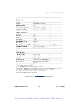
Page 87: ...nction Compensation Initial Accuracy 25 C3 0 25 C 0 75 C maximum Accuracy 5 C to 45 C 0 5 C 0 0125 C C Input Bias Current 25 nA Input Resistance Power On 5 M Power Off 40 k Overload 40 k Noise Input 0 1 Hz to 10 Hz Bandwidth 0 2 µV rms Output 100 kHz Bandwidth 500 µV rms Bandwidth 3 dB 4 Hz Output Rise Time 10 to 90 Span 200 ms Common Mode Voltage CMV Input to Output Continuous 1500 V rms maximum ...

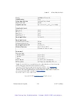
Page 88: ...C Operating 40 C to 85 C Storage 40 C to 85 C Relative Humidity 0 to 93 40 C noncondensing RFI Susceptibility 0 5 Span error 400 MHz 5 Watt 3 ft Includes the combined effects of repeatability hysteresis and nonlinearity and assumes RL 50 k Loads heavier than 50 k will degrade nonlinearity and gain temperature coefficient 2 1 µV C is equivalent to 0 02 C C for Type J thermocouples 0 025 C C for Typ...

Page 89: ...ces Refer to your E Series DAQ device user manual for more details Refer to Chapter 2 Configuring and Setting Up the SC 2311 to determine how to configure your SC 2311 to obtain power from either an E Series DAQ device or external power supply Table C 1 5B Series Current Requirements 5B Series Module Each Current Requirement at 5 VDC 5B30 30 mA 5B31 30 mA 5B40 30 mA 5B41 30 mA 5B32 30 mA 5B34 30 m...

Page 90: ... Current Requirements SSR Series Module Each Current Requirement at 5 VDC SSR IDC 5 10 mA SSR IAC 5 10 mA SSR IAC 5A 10 mA SSR ODC 5 10 mA SSR OAC 5 10 mA SSR OAC 5A 10 mA Table C 1 5B Series Current Requirements Continued 5B Series Module Each Current Requirement at 5 VDC Artisan Technology Group Quality Instrumentation Guaranteed 888 88 SOURCE www artisantg com ...

Page 91: ...s tutorials technical news as well as a community of developers ready to share their own techniques Customer Education National Instruments provides a number of alternatives to satisfy your training needs from self paced tutorials videos and interactive CDs to instructor led hands on courses at locations around the world Visit the Customer Education section of ni com for online course schedules sy...

Page 92: ...com Branch office Web sites provide up to date contact information support phone numbers e mail addresses and current events If you have searched the technical support resources on our Web site and still cannot find the answers you need contact your local office or National Instruments corporate Phone numbers for our worldwide offices are listed at the front of this manual Artisan Technology Group...

Page 93: ...o 103 M mega 106 G giga 109 t tera 1012 Numbers Symbols percent positive of or plus negative of or minus per degree Ω ohm A A amperes A D analog to digital AC alternating current AC coupled allowing the transmission of AC signals while blocking DC signals Artisan Technology Group Quality Instrumentation Guaranteed 888 88 SOURCE www artisantg com ...

Page 94: ... 1 hardware a property of an event that occurs at an arbitrary time without synchronization to a reference clock 2 software a property of a function that begins an operation and returns prior to the completion or termination of the operation attenuate to decrease the amplitude of a signal attenuation ratio the factor by which signal amplitude is decreased AWG American Wire Gauge B b bit one binary...

Page 95: ... form ports Ports usually consist of either four or eight digital channels channel clock the clock controlling the time interval between individual channel sampling within a scan Devices with simultaneous sampling do not have this clock Channel Wizard a utility incorporated into MAX that allows you to descriptively name physical channels in your system circuit trigger a condition for starting or s...

Page 96: ... analog trigger using software Also called software triggering conversion time the time required in an analog input or output system from the moment a channel is interrogated such as with a read instruction to the moment that accurate data is available counter timer a circuit that counts external pulses or clock pulses timing crosstalk an unwanted signal on one channel due to an input on a differe...

Page 97: ...tiple channels and conversion devices Plug in products PCMCIA cards and devices such as the DAQPad 1200 which connects to your computer parallel port are all examples of DAQ devices SCXI modules are distinct from devices with the exception of the SCXI 1200 which is a hybrid DIFF differential mode differential input an analog input consisting of two terminals both of which are isolated from compute...

Page 98: ...on or state of an analog or digital signal external trigger a voltage pulse from an external source that triggers an event such as A D conversion EXTREF external reference signal EXTSTROBE external strobe signal F false triggering triggering that occurs at an unintended time Fc frequency cutoff filtering a type of signal conditioning that allows you to filter unwanted signals from the signal you a...

Page 99: ...data at a known position in time relative to a trigger signal Hz hertz the number of scans read or updates written per second I I O input output the transfer of data to from a computer system involving communications channels operator interface devices and or data acquisition and control interfaces in inch or inches input impedance the measured resistance and capacitance between the input terminal...

Page 100: ...nd or from any input to the amplifier output or to the computer bus isothermal constructed to maintain constant temperature across area Isothermal construction of terminal blocks increases thermocouple measurement accuracy K k kilo the standard metric prefix for 1 000 or 103 used with units of measure such as volts hertz and meters K 1 kelvin 2 kilo the prefix for 1 024 or 210 used with B in quant...

Page 101: ...aled to measure physical phenomena LSB least significant bit M m meters M 1 Mega the standard metric prefix for 1 million or 106 when used with units of measure such as volts and hertz 2 mega the prefix for 1 048 576 or 220 when used with B to quantify data or computer memory Measurement Automation Explorer MAX a controlled centralized configuration environment that allows you to configure all of ...

Page 102: ...ystem ground Also called floating signal sources Some common example of nonreferenced signal sources are batteries transformers or thermocouples NRSE nonreferenced single ended mode all measurements are made with respect to a common NRSE measurement system reference but the voltage at this reference can vary with respect to the measurement system ground O onboard channels channels provided by the ...

Page 103: ...nternational Association peak to peak a measure of signal amplitude the difference between the highest and lowest excursions of the signal PFI programmable function input PGIA programmable gain instrumentation amplifier pipeline 1 a high performance processor structure in which the completion of an instruction is broken into its elements so that several elements can be processed simultaneously fro...

Page 104: ...curacy of an ADC It includes all nonlinearity and quantization errors It does not include offset and gain errors of the circuitry feeding the ADC resolution the smallest signal increment that can be detected by a measurement system Resolution can be expressed in bits in proportions or in percent of full scale For example a system has 12 bit resolution one part in 4 096 resolution and 0 0244 of ful...

Page 105: ... input samples in a scan is equal to the number of channels in the input group For example one pulse from the scan clock produces one scan which acquires one new sample from every analog input channel in the group scan clock the clock controlling the time interval between scans On devices with interval scanning support for example the PCI 6052E this clock gates the channel clock on and off On devi...

Page 106: ... is better and the voltage driving ability of current sources higher is better SS simultaneous sampling a property of a system in which each input or output channel is digitized or updated at the same instant SSR solid state relay STARTSCAN start scan signal STC system timing controller strain gauge a thin conductor which is attached to a material that detects stress or vibrations in that material...

Page 107: ...a type of signal conditioning that uses external voltages and currents to excite the circuitry of a signal conditioning system into measuring physical phenomena TRIG trigger signal trigger any event that causes or starts some form of data capture TTL transistor transistor logic U unipolar a signal range that is always positive for example 0 to 10 V update the output equivalent of a scan One or mor...

Page 108: ... panel user interface and a block diagram program VIH volts input high VIL volts input low Vin volts in VIN voltage input signal VOH volts output high VOL volts output low Vref reference voltage VSS voltage supply signal W waveform multiple voltage readings taken at a specific sampling rate working voltage the highest voltage that should be applied to a product during normal use normally well unde...

Page 109: ... 3 3 specifications B 27 to B 28 5B38 strain gauge input module functional description B 29 to B 31 overview 3 4 specifications B 31 to B 33 5B40 5B41 voltage input modules functional description B 34 to B 35 overview 3 2 specifications B 36 to B 37 5B42 process current input module with 20 VDC loop functional description B 38 to B 39 overview 3 4 specifications B 40 to B 41 5B45 46 frequency inpu...

Page 110: ...I Developer Zone D 1 P parts locator diagram for SC 2311 shielded carrier 2 3 physical specifications SC 2311 shielded carrier A 1 power requirements for SC 2311 shielded carrier with 5B and SSR series modules C 1 to C 2 R rack mount kit 2 9 to 2 10 S safety information 2 5 to 2 6 safety specifications SC 2311 shielded carrier A 2 SC 2311 shielded carrier configuration 2 1 to 2 6 I O panelettes 2 ...

Page 111: ... I O A 1 electromagnetic compatibility A 2 environment A 2 physical A 1 safety A 2 SSR Series modules A 3 to A 4 input module characteristics table A 3 output module characteristics table A 4 SSR Series modules input modules 4 1 to 4 3 SSR IAC 5 120 VAC 4 2 SSR IAC 5A 240 VAC 4 2 SSR IDC 5 3 32 VDC 4 3 output modules 4 3 to 4 6 SSR OAC 5 120 VAC 4 4 to 4 5 SSR OAC 5A 240 VAC 4 5 SSR ODC 5 3 60 DVC...

Page 112: ...l service in house repair center WE BUY USED EQUIPMENT Sell your excess underutilized and idle used equipment We also offer credit for buy backs and trade ins www artisantg com WeBuyEquipment REMOTE INSPECTION Remotely inspect equipment before purchasing with our interactive website at www instraview com LOOKING FOR MORE INFORMATION Visit us on the web at www artisantg com for more information on ...

Reviews: