


©
National Instruments Corporation
3
NI SHC68-C68-D5 Cable Installation Instructions
3.
Connect the other end of the cable to your supported NI high-speed DIO device. Refer to Table 1
in the
Cable Configuration
section to determine how to connect signals to your application.
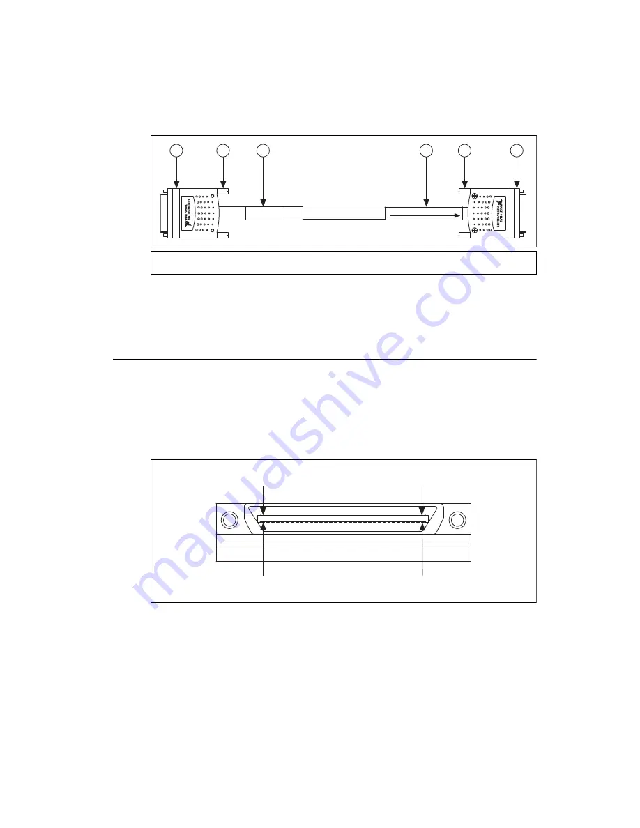
Figure 2.
NI SHC68-C68-D5 Cable
4.
Tighten the thumbscrews on the cable.
5.
If you have not already done so, connect the NI 2515 to the rest of your system. Refer to the
NI Switches Help
for more information about connecting the NI 2515 to your system.
Cable Configuration
Connectors
The cable connects two 68-position male VHDCI connectors. The connector labeled
CONNECTS TO
NI 2515
provides connection to the switch module. The second connector provides connection to a
supported NI high-speed DIO device. Figure 3 shows the pinout for the connectors.
Use the pinout and the pin assignments listed in Table 1 to determine how to connect signals to your
application using the NI SHC68-C68-D5 cable.
Figure 3.
NI SHC68-C68-D5 Mating Connector
1
NI SHC68-C68-D5 Connectors
2
Thumbscrews
3
Connects to Supported NI High-Speed DIO Device
4
CONNECTS TO NI 2515
Label
CONNECT
S
TO NI 2515
3
4
2
1
2
1
3
0 VDC CAT I
Pin 1
Pin
3
5
Pin 6
8
Pin
3
4


