background image

©

 National Instruments Corporation

21

NI 6509 User Guide and Specifications

Internally, the filter uses two clocks: the sample clock and the filter clock. 
The sample clock has a frequency of 48 MHz that corresponds to a period 
of 20.83 ns. The filter clock is generated by a counter and has a period equal 
to one half of the specified timing interval. The input signal is sampled on 
each rising edge of the sample clock. However, a change in the input signal 
is recognized only if it maintains its new state for at least two consecutive 
rising edges of the filter clock.

The filter clock is programmable and allows you to control how long a 
pulse must last to be recognized. The sample clock provides a fast sample 
rate to ensure that input pulses remain constant between filter clocks.

Digital Filtering Example

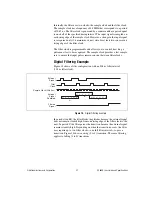
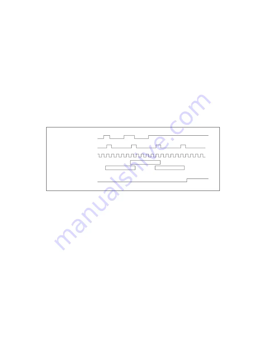
Figure 18 shows a filter configuration with an 208 ns filter interval 
(104 ns filter clock).

Figure 18.  

Digital Filtering Example

In periods A and B, the filter blocks the glitches because the external signal 
does not remain steadily high from one rising edge of the filter clock to the 
next. In period C, the filter passes the transition because the external signal 
remains steadily high. Depending on when the transition occurs, the filter 
may require up to two filter clocks—one full filter interval—to pass a 
transition. Figure 18 shows a rising (0 to 1) transition. The same filtering 
applies to falling (1 to 0) transitions.

Sa

mple Clock (20.8

3

 n

s

)

H H

H H H

H

L

L

L

H

H L

L

L

H

A

B

C

H

H

H

Extern

a

l

S

ign

a

l

Filter

Clock

Extern

a

l

S

ign

a

l

Sa

mpled

Filtered

S

ign

a

l

Summary of Contents for USB-6509

Page 1: ...er supply that can increase the I O drive strength Contents Getting Started 2 Installing Software 2 Installing the Hardware 3 USB Cable Strain Relief 3 Mounting the NI USB 6509 3 Desktop Use 3 DIN Rai...

Page 2: ...31 Getting Started NI USB 6509 devices feature up to 96 bidirectional per port static DIO lines If you have not already installed your device refer to the NI DAQmx for USB Devices Getting Started Gui...

Page 3: ...e groove that matches your USB cable size as shown in Figure 1 Zip Tie Method Thread a zip tie through the zip tie bar on the underside of the NI USB 6509 and tighten around the USB cable as shown in...

Page 4: ...el mounting the NI USB 6509 or stacking multiple NI USB 6509 devices Figure 2 Applying Rubber Feet to the NI USB 6509 DIN Rail Mounting The DIN rail mounting kit part number 779689 01 not included in...

Page 5: ...section before panel mounting the NI USB 6509 1 Go to ni com info and enter the info code rd3233 to download and print the panel mounting template PDF 2 Using the template mark the bottom point and t...

Page 6: ...witch 2 LED 3 Recessed USB Port 4 DC Power Jack Industrial Digital I O Control FPGA DIO Lines Programmable Power Up States Watchdog Timer Change Detection Digital Filtering USB Interface Data Control...

Page 7: ...or USB Getting Started Guide for more information NI DAQmx includes a collection of programming examples to help you get started developing an application You can modify example code and save it in an...

Page 8: ...tion about creating and configuring channels tasks and scales using the DAQ Assistant I O Connector The 100 pin high density SCSI connector on the NI USB 6509 provides access to 96 digital inputs and...

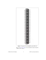
Page 9: ...2 1 P5 2 P2 2 P5 3 P2 3 P5 4 P2 4 P5 5 P2 5 P5 6 P2 6 P5 7 5 V P9 0 P6 0 P9 1 P6 1 P9 2 P6 2 P9 3 P6 3 P9 4 P6 4 P9 5 P6 5 P9 6 P6 6 P9 7 P6 7 P10 0 P7 0 P10 1 P7 1 P10 2 P7 2 P10 3 P7 3 P10 4 P7 4 P1...

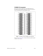
Page 10: ...P2 5 P2 6 P2 7 GND P3 1 P3 2 P3 4 P3 5 P3 6 P3 7 P3 0 P3 3 P4 0 P4 1 P4 2 P4 3 P4 4 P4 5 P4 6 P4 7 P5 0 P5 1 P5 2 P5 3 P5 4 P5 5 P5 6 P5 7 49 50 47 48 45 46 43 44 41 42 39 40 37 38 35 36 33 34 31 32...

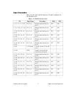
Page 11: ...rt 4 P4 7 P4 0 33 35 37 39 41 43 45 47 P0 7 0 Bi directional data lines for port 0 P0 7 P0 0 34 36 38 40 42 44 46 48 P3 7 0 Bi directional data lines for port 3 P3 7 P3 0 49 99 5 V supply 5 Volts prov...

Page 12: ...information on the I O pull resistor refer to the I O Pull Up Pull Down Resistor section Figure 8 shows the circuitry of one DIO line Figure 8 NI USB 6509 Digital I O Circuitry The voltage input and...

Page 13: ...ine can be independently configured for high impedance input high output or low output after power up For more information refer to the Programmable Power Up States section When the device is powered...

Page 14: ...RL V I where V 0 8 V is the voltage across RL I 91 A is the maximum leakage current from the device at low input therefore RL 8 8 k is the 0 8 V 91 A This resistor value 8 8 k provides a maximum of 0...

Page 15: ...calculate the largest possible load to maintain a logic high level of 2 V and supply the maximum sink current I V I RL RL V I where V 5 V 2 V 3 V is the voltage across RL I 91 A is the maximum leakage...

Page 16: ...nformation refer to the Optional 12 VDC Power Supply Installation section DIO Signal Connection Figure 11 shows an example of signal connections for three typical digital I O applications Port 0 is co...

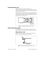
Page 17: ...mount the flyback diode within 18 inches of the load Figure 12 shows an example of using an external flyback diode to protect inductive loads Figure 12 Limiting Flyback Voltages at the Inductive Load...

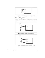
Page 18: ...and 16 are examples of connecting the NI USB 6509 to a relay that requires more than 24 mA of current These examples use an additional transistor circuit Figure 15 NI USB 6509 Sinking Connection Exam...

Page 19: ...09 complete the following steps 1 Ensure that the device is powered off by unplugging the USB cable from the device 2 After the device is powered off and unplugged remove the plastic cap on the DC jac...

Page 20: ...mmable power up states change detection and a watchdog timer Digital Filtering Use the digital filter option available on the NI USB 6509 input lines to eliminate glitches on input data When used with...

Page 21: ...clock provides a fast sample rate to ensure that input pulses remain constant between filter clocks Digital Filtering Example Figure 18 shows a filter configuration with an 208 ns filter interval 104...

Page 22: ...ange occurs on any input line The NI USB 6509 can monitor changes on selected input lines or on all input lines It can monitor for rising edges 0 to 1 falling edges 1 to 0 or both When an input change...

Page 23: ...ports no changes for bits 3 and 2 After receiving notification of a change you can read the port to determine the current values of all eight lines You cannot read the state of any lines that are conf...

Page 24: ...e products available for use with the NI USB 6509 For more information about optional equipment available from National Instruments visit ni com Specifications This section lists the specifications of...

Page 25: ...igital Output Characteristics Level Min Max Input voltage 0 V 5 0 V Input low voltage Input high voltage Input low current Vin 0 V Input high current Vin 5 V 2 0 V 0 8 V 91 0 A 91 0 A Level Min Typ Ma...

Page 26: ...tomer replaceable If the fuse is blown return the device to NI for repair Bus Interface USB USB 2 0 Hi Speed or full speed1 Power Requirement USB Input voltage 4 5 to 5 25 V in configured state No loa...

Page 27: ...ental The NI USB 6509 device is intended for indoor use only Operating temperature IEC 60068 2 1 and IEC 60068 2 2 0 to 55 C Operating humidity IEC 60068 2 56 10 to 90 RH noncondensing Maximum altitud...

Page 28: ...sible manner NI recognizes that eliminating certain hazardous substances from our products is beneficial not only to the environment but also to NI customers For additional environmental information r...

Page 29: ...ed to clean the device use a dry cloth Make sure that the device is completely dry and free from contaminants before returning it to service Operate the device only at or below Pollution Degree 2 Poll...

Page 30: ...all outlet for example 115 V for U S or 230 V for Europe Examples of Measurement Category II are measurements performed on household appliances portable tools and similar E Series devices Measurement...

Page 31: ...supports calibration you can obtain the calibration certificate for your product at ni com calibration National Instruments corporate headquarters is located at 11500 North Mopac Expressway Austin Te...

Reviews: