58
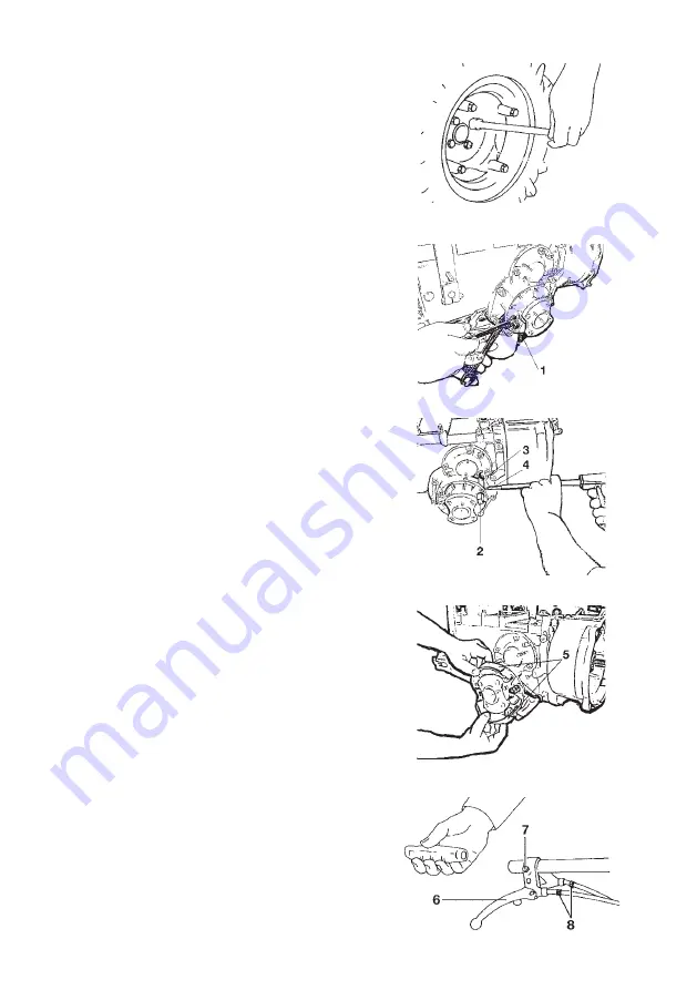
Fig. 15a
Fig. 15b
Fig. 15c
Fig. 15d
Fig. 15e
BRAKE ASSEMBLY INSTRUCTIONS
(Fig. 15)
1)
Place the engine on a stable support.
2)
Unscrew the wheel fixing screws (Fig. 15a
).
3)
Lift the engine driven cultivator from the
power take-off side and completely remove
the wheels.
4)
From the brake kit, take the brake suppor
-
ting threaded stud (1) and the relevant nut
and mount it into its seat (power take-off side).
Fully tighten with two wrenches (fig. 15b).
5)
Insert the block opening stud (2) into its
seat, engage the pin control lever (3) and,
by using a drift and a hammer, fix it with pin
(4) into the stud (fig. 15c).
CAUTION: every stud has a right or left
side as mentioned on it.
We remind you that the machine right and
left sides are identified by the operator
working from the machine handlebar with
the steering column in milling position.
6)
Insert the brake shoes (5) on the appro
-
priate half-support pins.
When assembling, make sure that the brake
shoe springs are in correspondence with the
axle shaft undercuts(fig. 15 d).
7)
Assemble the brake drum (11) and wheel
by means of fixing screws (1).
8)
After having removed the handlebar grip,
insert lever (6) and lock it in its position by
using screw (7).
9)
Screw adjuster (8) on lever (6).
10)
Insert the wire on the brake lever 6) and
on the brake shoe lever control (3).
11)
Adjust the lever clearance to 8mm by opera
-
ting on the wire clamp and on adjuster (8).
12)
Reassemble the grip (Fig. 15e).


