background image

1

Instruction Manual

US

HE.13575_A © 06/2010

PC-280

1

Instruction Manual

Tab. 2 (see page I, pic. 1)

Pos.

Description

Function

1

LED (red)

Indicator for battery charge 
control, tool functions and 
faults

2

Retract slide

Slide to retract the drive rollers 
in case of an error or emer-
gency

3

Battery 
cartridge

Rechargeable 3 Ah Li-Ion 
battery (PC-7L)

Optional:

adapter PC-9L

4

Trigger

Operating switch 
to start the motor

5

LED (white)

To illuminate the working area

6

Pin

Bolt to lock the pressing jaws

7

Pressing jaws

To press the fi tting on the 
pipes

8

Pressing head

Reception for the pressing 
jaws

9

Protection 
sleeve

Adaptable protection sleeve for 
the intended application of dif-
ferent pressing jaws / - chains

10

Housing

Ergonomically formed plastic 
housing in a 2-Component 
design for perfect handling 

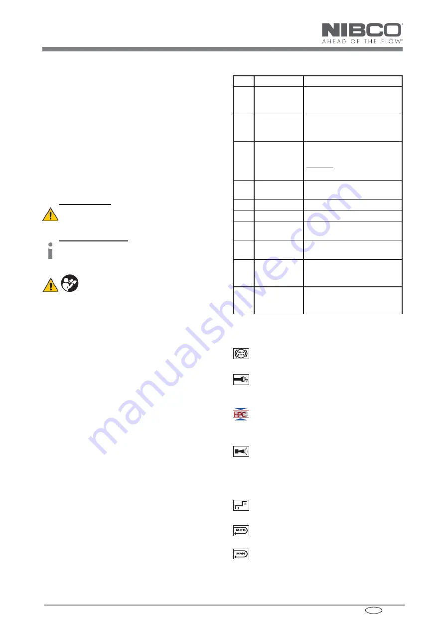
2.2  Brief description of the important 

features of the unit


Safety features:

The unit is equipped with a special brake which in-
stantly stops the forward motion of the piston/dies 
when the trigger is released.

A white LED illuminates the working space after ac-

tivating the trigger. It automatically switches off 10 
sec. after releasing the trigger. This feature can be 
deactivated (see page V)
Hydraulic Pressure Check, HPC for short, monitors 
the oil pressure in the tool’s oil circuit, hence ensur-
ing a continuous, consistent press quality.
During each pressing cycle, the achieved pressing 
pressure is determined by a pressure sensor and 
compared to the required minimum value. An au-
dible warning signal sounds if the achieved pres-
sure differs from the specified working pressure. 
The user will know immediately that the fi tting must 
be checked and repressed or replaced as required.


Functional features:

The unit is equipped with a double piston pump 
which is characterized by a rapid approach of the 
rollers towards the jaws and power speeds.
The hydraulic unit incorporates an automatic retrac-
tion which returns the piston into its starting position 
when the maximum operating pressure is reached.

A manual retraction allows the user to return the pis-

ton into the starting position in case of an incorrect 
compression.

Index

1.  

Introduction

2.  

Description of the pressing tool

2.1  Components of the unit
2.2   Brief description of the important features 

of the unit

3.  

Remarks with respect to the intended use

3.1   Operation of the unit
3.2   Explanation of the application range
3.3 Installation 

instructions

3.4   Service and maintenance instructions
4. Troubleshooting
5.  

Technical data 

Symbols

Safety warnings

Please do not disregard these instructions in or-
der to avoid human injuries and environmental 
damage.

Operational warnings

Please do not disregard them to avoid dama-
ging the tool.

1.   Introduction

Before starting to use the tool please read 

the instruction manual carefully.

Use this tool exclusively for its determined use respecting 
all international and domestic health and safety regulati-
ons.

Use this tool exclusively for its determined use.

This instruction manual has to be carried along during the 
entire life span of the tool.

The operator has

•  to guarantee the availability of the instruction manual 

for 
the user and

•  to make sure, that the user has read and understood 

the instruction manual.

2.   Description of the pressing tool

2.1  Components of the tool

The electric-hydraulic tool is hand guided and consists of 
the following components:

Summary of Contents for PC-280

Page 1: ...eck Serialnummer Hydraulic Pressure Check PC 280 NIBCO INC World Headquarters 1516 Middlebury Street Elkhart IN 46516 USA Hydraulic Pressure Check Serialnummer HE 13575_A 06 2010 TE 2 US Instruction Manual Battery powered Pressing Tool ...

Page 2: ...30 RAL2 optional NG2230 1 8 9 10 6 2 7 4 HE 15333 HE 13575_A 06 2010 PC 280 I Bedienungsanleitung Instruction Manual 3 PC 7L optional PC 9L 5 1 6 2 4 3 PC 7L optional PC 9L 5 1 8 9 10 6 2 7 pic 1 see Tab 3 4 HE 15333 Components identified on page 1 US ...

Page 3: ...II Bedienungsanleitung Instruction Manual PC 7L 22 min 50 104 F CLICK 1 2 3 4 5 5 304711 batch e g 304711 CV datecode e g C 2009 V July 142 consecutive e g 142 tool 142 pic 2 PC 280 Voltage 18V DC Thrust 32 kN HE 13565 pic 5 pic 6 pic 7 pic 8 pic 9 pic 10 Li ion pic 11 884676B996 884598C990 pic 12 1 2 1 2 pic 4 pic 3 HE 13564 NIBCO INC World Headquarters 1516 Middlebury Street Elkhart IN 46516 USA...

Page 4: ...dienungsanleitung Instruction Manual 45 1 2 1 350 CLICK 2 OIL HE 13575_A 06 2010 PC 280 III Bedienungsanleitung Instruction Manual 45 1 2 OIL pic 14 pic 16 pic 15 pic 17 45 1 2 1 CLICK 2 pic 13 pic 18 OIL 1 2 ...

Page 5: ...2 1 CLICK 2 CLICK OIL HE 13575_A 06 2010 PC 280 IV Bedienungsanleitung Instruction Manual 45 1 2 1 CLICK K K K K K K K K K K K K K K K K K K K K K K K K K K K K 2 OIL pic 20 pic 22 pic 19 pic 21 pic 23 1 2 45 1 2 1 CLICK 2 pic 24 CLICK CLICK OIL 1 2 ...

Page 6: ...V Bedienungsanleitung Instruction Manual on off PRESS PRESS HE 13575_A 06 2010 PC 280 V Bedienungsanleitung Instruction Manual pic 25 on off PRESS PRESS PRESS PRESS PRESS ...

Page 7: ...13575_A 06 2010 PC 280 VI Bedienungsanleitung Instruction Manual pic 26 pic 27 pic 28 Adapter jaw not included in scope of delivery space for jaw available in tool case pic 29 Adapter jaw not included in scope of delivery space for jaw available in tool case ...

Page 8: ...heck 20 sec 2Hz after working cycle 20 sec 5Hz while exceeding the temp limit Unit too hot 20 sec 20 sec 2Hz after working cycle 1 x after working cycle Error the required pressure has not been reached The operator has interrupted the pressing cycle manually while the motor was not running 3 x 3 x after working cycle Serious Error The pressure has not been reached while the motor was running ...

Page 9: ... The user will know immediately that the fitting must be checked and repressed or replaced as required Functional features The unit is equipped with a double piston pump which is characterized by a rapid approach of the rollers towards the jaws and power speeds The hydraulic unit incorporates an automatic retrac tion which returns the piston into its starting position when the maximum operating pr...

Page 10: ... 3 1 Operation of the tool After having selected the right pressing jaw for the inten ded application page VI pic 25 the jaw must be exami ned in terms of possible damage dirt in the compression area and ware When using competitor products the user has to make sure that the jaw complies with our tool Dependant on the type of jaws the protection sleeve page III pic 13 can be used to adapt to the si...

Page 11: ...ompati bility statement Attention Do not use bent or damaged pressing jaws For your job on the location we recommend the accesso ries shown on page VI in pic 25 3 4 Service and maintenance instructions The reliable performance of the tool is dependent on ca reful treatment and service This represents an important condition to ensure a lasting connection For optimal per formance the tool should be ...

Page 12: ...us fault If this fault occures repeatedly return the unit to an Authorized Service Center ASC Do not open it and damage the seal of the tool In case of a one time occurence the fitting has to be dismantled or pressed a second time 5 Technical Data Weight incl battery 9 5 lbs Thrust force linear 32 kN min Driving motor direct current permanent field Battery voltage 18 V DC Battery capacity 3 Ah PC ...

Reviews: