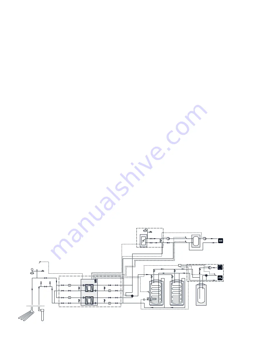
Outline diagram
Explanation
External additional heat
EB1
Accessory card (AXC 50)
AA5
Expansion vessel, closed
CM5
External electrical additional heat
EB1
Safety valve, heating medium side
FL10
Shut-off valve, heating medium side
QM42 -
QM43
Trim valve
RN11
Heat pump system (Master)
EB100
Temperature sensor, outdoor
BT1
Temperature sensor, hot water
BT6
Temperature sensor, external flow line
BT25
Temperature sensor, external return line
BT71
Heat pump, F1345
EB100
Cooling module A
EP14
Cooling module B
EP15
Safety valve, collector side
FL10 -
FL11
Safety valve, heating medium side
FL12 -
FL13
Particle filter
HQ12 -
HQ15
Shut-off valve, brine side
QM50 -
QM53
Shut-off valve, heating medium side
QM54 -
QM57
Reversing valve, heating/hot water
QN10
Non-return valve
RM10 -
RM13
Hot water comfort
QZ1
Accessory card (AXC 50)
AA5
Temperature sensor, outgoing hot water
BT70
Immersion heater
EB2
Hot water heater
EB10
Mixer valve, hot water
FQ1
Circulation pump, domestic hot water circulation
GP11
Auxiliary relay, immersion heater
KA1
Non-return valve
RM23
Trim valve
RN20
Connection box
XD1
Miscel-
laneous
Manometer, brine side
BP6
Expansion vessel, brine side
CM3
Accumulator tank with solar coil
CP10,
CP11
Buffer vessel, UKV
CP20
Safety valve, brine
FL3
Circulation pump, heating medium external
GP10
Circulation pump, heating medium external
GP18
Venting valve, brine side
QM21
Shut off valve, brine return
QM33
Shut off valve, brine flow
QM34
Non-return valve
RM21
Trim valves
RN60 -
RN63
Connection, filling brine
XL27 -
XL28
Designations according to standards 81346-1 and 81346-
2.
Outline diagram F1345 with AXC 50 and hot water comfort
-EB100-BT71
-EP12
-CM3
P
-BP6
-QM21 -FL3
-XL28
-XL27
-QM33
-QM34
-EB100-BT1
-EB100-BT25
-HQ15
-HQ14
-RM12
-RM13
-QM54
-FL12
-QM55
-QM56
-QM57
-FL13
-HQ13
-RM11
-HQ12
-RM10
-QM50
-QM51
-FL10
-QM52
-QM53
-FL11
-EB100
-EP15
-EP14
-EB100
-EB100
-BT6
-CP10
-QZ1-EB2
-QZ1-XD1
-QZ1-KA1
-RN63
-RN62
-CP11
-RN60
-RN61
-EB100-QN10
-QZ1-AA5
-GP11
-RN20
-RM23
-EB10
-FQ1
-BT70
-QZ1
-CM5
-FL10
-QM42
-QM43 -RN11
-EB1
-EB1
-RM21
-GP18
-CP20
-GP10
21
Chapter 6 |
Hot water comfort
AXC 50
Summary of Contents for AXC 50
Page 1: ...Installer manual LEK AXC 50 Accessories IHB GB 1222 1 231158...
Page 2: ......
Page 10: ...Electrical circuit diagram AXC 50 Chapter 3 Shunt controlled additional heat 8...
Page 15: ...Electrical circuit diagram 13 Chapter 4 Step controlled additional heat AXC 50...
Page 21: ...Electrical circuit diagram 19 Chapter 5 Extra climate system AXC 50...
Page 26: ...Electrical circuit diagram AXC 50 Chapter 6 Hot water comfort 24...
Page 29: ...Electrical circuit diagram 27 Chapter 7 Groundwater pump AXC 50...
Page 34: ...Electrical circuit diagram AXC 50 Chapter 8 Passive cooling 4 pipe 32...
Page 40: ...Electrical circuit diagram AXC 50 Chapter 9 Passive cooling 2 pipe 38...
Page 46: ...Electrical circuit diagram AXC 50 Chapter 10 Passive active cooling 2 pipe 44...
Page 47: ......
Page 48: ...NIBE AB Sweden Hannabadsv gen 5 Box 14 SE 285 21 Markaryd info nibe se www nibe eu 231158...


