37
www.climacoolcorp.com
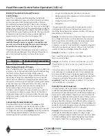
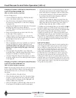
Head Pressure Control Valve Operation (LAC-10)
WARNING:
Serious injury could result from an explosion
caused by the rapid expansion of trapped liquid refrigerant
subjected to high temperature .
ALWAYS OPEN OR VENT
THE SYSTEM BEFORE APPLYING HEAT TO REMOVE SYSTEM
COMPONENTS.
Break the element charging cap tube on
valve dome by hand or with a clean cut tool . DO NOT use
side cutters, which may seal the opening .
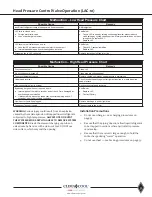
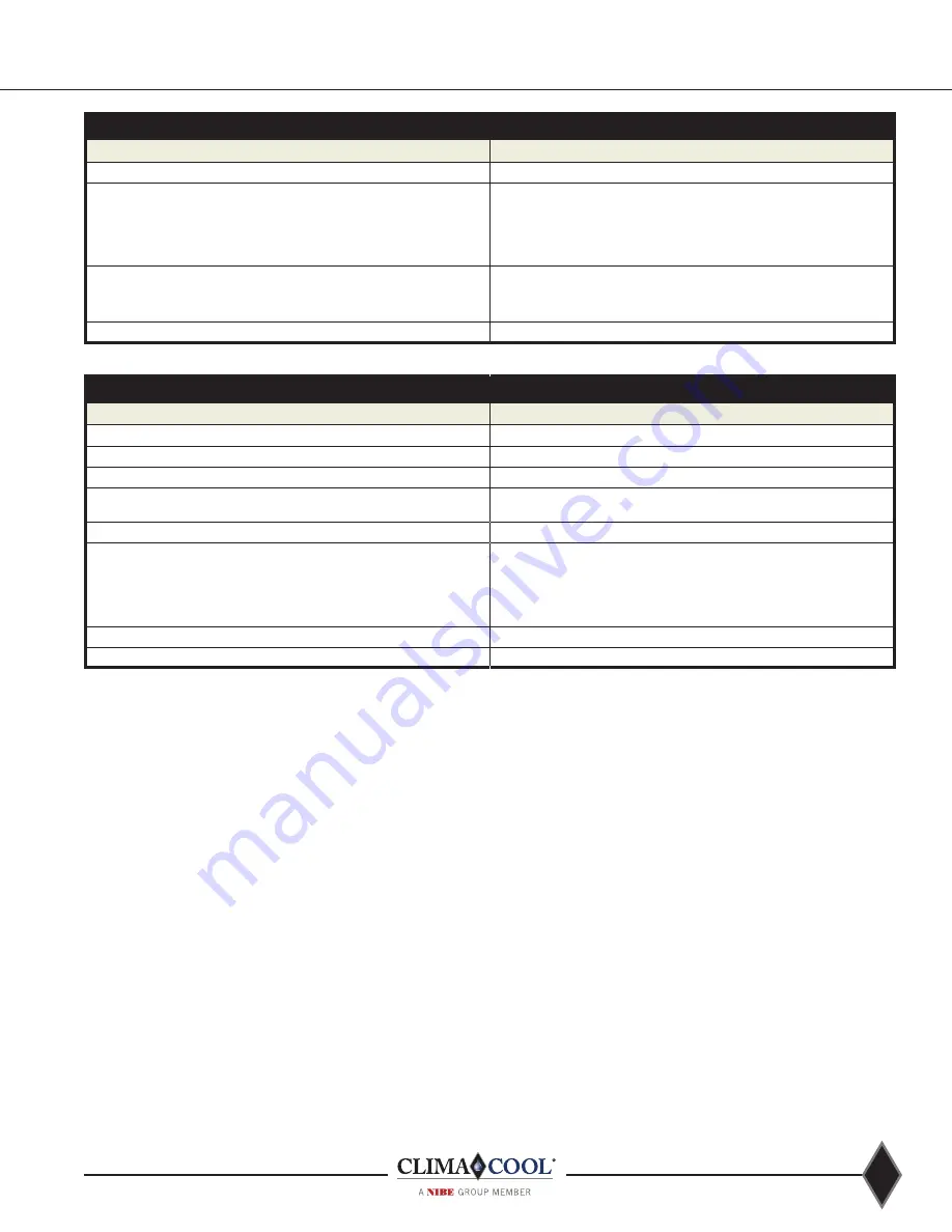
Malfunction – Low Head Pressure Chart
Possible Cause
Remedy
Insufficient refrigerant charge to adequately flood condenser
Add refrigerant
LAC fails to close due to:
a. Foreign material in valve
b. Loss of air charge in element
See Below:
a. Cause LAC to open by raising condensing/receiver pressure above
valve setting by cycling condenser fan. If foreign material does not pass
through valve, replace LAC
b. Replace LAC
LAC receiver port fails to open due to:
a. Less that 20 psi pressure drop across inlet to receiver port
b. Internal parts damaged by overheating when installed
See Below:
a. Check LAC causes/remedies
b. Replace LAC
Discharge line to LAC restricted
Remove restriction in fitting(s) or line
Malfunction – High Head Pressure Chart
Possible Cause
Remedy
Dirty condenser coil
Clean coil
Air on condenser blocked off
Clean area around condenser
Too much refrigerant charge
Remove charge until proper head pressure is maintained
Undersized receiver
Check receiver capacity against refrigerant required to maintain desired
head pressure
Non-condensibles (air) in system
Recover, evacuate and recharge
Bypassing hot gas when not required due to:
a. Internal parts of the Inlet to receiver port of the LAC are damaged by
overheating when installed
b. If pressure drop across the condenser, associated piping and LAC
exceeds 14 psi under full load conditions
See Below:
a. Replace LAC
b. Contact Factory
Liquid port or liquid line plugged
Remove blockage in port or liquid line
Condenser fans not running
Repair or replace fan motor
Installation Precautions
1 .
Do not overcharge — see charging procedures on
page 34 .
2 .
Be sure that the piping does not allow liquid refrigerant
to be trapped in sections where hydrostatic pressure
can develop .
3 .
Be sure that the receiver is large enough to hold the
entire charge during “warm” operation .
4 .
Do not overheat — see brazing procedures on page 33 .
Summary of Contents for CLIMACOOL UCR 30
Page 19: ...17 www climacoolcorp com Voltage Phase Monitor Wiring Diagram...
Page 29: ...27 www climacoolcorp com Evaporator Water Pressure Drop Charts...
Page 30: ...28 www climacoolcorp com Glycol Performance Adjustments Factor Charts...
Page 78: ...76 www climacoolcorp com Wiring Diagram...
Page 79: ...77 www climacoolcorp com Wiring Diagram...
Page 80: ...78 www climacoolcorp com Wiring Diagram CoolLogic Control Panel...
Page 81: ...79 www climacoolcorp com Wiring Diagram CoolLogic Control Panel...

