5
www.climacoolcorp.com
Ul�
m
at
e Chiller Solu�o
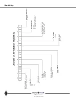
n Model Key
REJECTIO
N MEANS
R = Re
mote
Conde
nser (Air Cool
ed)
030
E
0
C
A
S
A
R
S
A
F
CU
1 2
3
4 5 6
7
8
9
10
11
12
13
14
15
NOMINAL TONS
030 050 070
DESIGN SERIES
A
VOLTAGE
F = 460/3/60 H = 208-230/3/60 N = 575/03/60
CONTROLS & ELECTRICAL
A = Standard (DDC)
COMPRESSOR TY
PE
S = Scrol
l
MODEL CONFIGURATION
S = Standard
REJECTIO
N OPTIONS
0 = (N
one
)
B = Hot Gas Bypass - Both Circuits
C = Compressor Isola�on Valve
s
WATER ISOLATION VALVES
E = Evap. Motorized Valves M = Manual Evap Valves
APPLICATION
C = Cooling
REFRIGERANT
A = R-410A
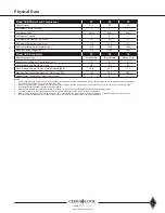
Physical Data
Model UCR Module and Compressor
30
50
70
Capacity (tons)
1
27.4
45
59
Refrigerant Circuits (quantity)
2
2
2
Compressor Type
Scroll
Scroll
Scroll
Compressor Quantity
2
2
2
Compressor Nominal hp (per circuit)
15
25
35
Oil Factory Charge (per circuit) (oz.)
110
230
213
Module Operating Weight w/Water (lbs.)
2
1265
1945
2085
Module Shipping Weight (lbs.)
3
1170
1785
1925
Model UCR Evaporator
30
50
70
Heat Exchanger Type
Brazed Plate
Brazed Plate
Brazed Plate
Independent Refrigerant Circuits (quantity)
2
2
2
Water Storage Volume HX Only (gals.)
2.8
5.1
6.5
Water Storage Volume HX Plus 6" Main Headers (gals.)
12.8
15.7
17.1
Maximum Design Working Pressure - Water Side (PSI)
300
300
300
Header Water Connections - Inlet/Outlet (inches)
4
6
6
6
Notes:
1.
Unit tonnage ARI rating conditions: 44°F leaving chilled water temperature, and 2.4 GPM per ton through the evaporator; 95°F entering condenser air temperature
(dry bulb); 30°F condenser “TD” and 15°F liquid subcooling.
2. Module operational weight includes water, compressor oil, and refrigerant charge. Multiply times the number of modules for a total system operational weight.
3. Unit shipping weight includes compressor oil and packaging.
4.
Main header water/fluid connections are ASME, 6” schedule 40 pipe with grooved couplings, 300 psig maximum working pressure.
5.
The minimum/maximum flow rates are based on a temperature differential of 5.5°F to 20°F through the evaporator.
6.
Minimum chiller unloading percent can be as low as 4.8% of total systems. Calculate system unloading by dividing ½ of smallest module by total system tons.
7.
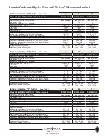
Remote condensers shipped with a nitrogen holding charge. See page 32 for estimated field charging of refrigerant.
Summary of Contents for CLIMACOOL UCR 30
Page 19: ...17 www climacoolcorp com Voltage Phase Monitor Wiring Diagram...
Page 29: ...27 www climacoolcorp com Evaporator Water Pressure Drop Charts...
Page 30: ...28 www climacoolcorp com Glycol Performance Adjustments Factor Charts...
Page 78: ...76 www climacoolcorp com Wiring Diagram...
Page 79: ...77 www climacoolcorp com Wiring Diagram...
Page 80: ...78 www climacoolcorp com Wiring Diagram CoolLogic Control Panel...
Page 81: ...79 www climacoolcorp com Wiring Diagram CoolLogic Control Panel...


