73
www.climacoolcorp.com
Basket Strainers
The correct size of Basket Strainer is determined by its job
function, not by the size of the pipeline .
Pre Installation Checklist:
1 .
Inspect the basket strainer’s flange ends and the
pipeline’s mating flanges to ensure gasket surfaces are
free of defects . The pipeline should also be checked for
proper alignment . Strainers should never be utilized to
realign an existing piping system .
2 .
Ensure that the pipeline’s mating flanges are the same
type as the basket strainer being installed . Raised face
flange ends cannot be mated to flat face flange ends.
3 .
Ensure that the pipeline setup allows a horizontal
installation of the basket strainer .
4 .
If pipeline strain is a concern when installing larger
basket strainers (6” and above), a concrete or steel pad
should be used to provide additional support . Larger
basket strainers can also be fitted with legs to assist in
reducing strain on the pipeline .
5 .
If the basket strainer is to be located on the discharge
side of a pump, then a safety release valve must be
installed between the basket strainer and the pump .
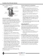
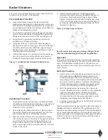
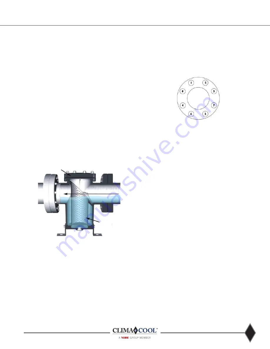
Figure 36 - Installed Basket Strainer with Bolted Cover
Basket
Strainer
Cover
Basket
Strainer
Screen
Pipeline Flow
Installation Procedure:
1 .
To provide for easier maintenance, the basket strainer
should be located where the drain plug can be removed
and where there is ample space above the basket
strainer for screen removal .
2 .
Before placing the basket strainer into place, support
the existing pipeline with pipe supports near the inlet
and outlet connections of the basket strainer .
3 .
Place the basket strainer into the pipeline ensuring
that the flow arrow on the body of the basket strainer
is pointing in the direction of the pipeline flow. For
large or heavy strainers, lift the basket strainer into
place using slings positioned underneath the inlet and
outlet connections .
4 .
Install a standard ANSI (1/8” thick) flange gasket
between the basket strainer and pipeline flanges, on
both sides. Install lubricated flange bolts and hand
tighten . Flange bolts should then be tightened, using
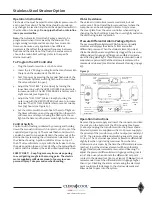
a star or crisscross pattern to evenly load the bolts, in
accordance with established piping standards . This is
illustrated in figure 37.
Figure 37: Bolting Sequence Pattern
Note: Excessive bolt torque may damage flanges. Please
refer to established flange bolt torques for guidelines.
Operation
Once proper installation has been successfully completed,
start the system gradually, at start up as well as after shut
down . This eliminates sudden shock to the strainer and
other equipment in the line . This is extremely important for
steam service .
Start-Up Procedure
1 .
Remove air from the pipeline by opening the vent near
the basket strainer .
Note:
With piping systems that
contain fluids other than water or when the working
temperature is above 120°F, fluid must be drained to safe
area, away from the operator . Operators should always
be fitted with appropriate equipment (goggles, gloves,
vests etc .) when venting or servicing is performed .
2 .
Start the piping system by opening the outlet valve
nearest the basket strainer’s outlet first. Then gradually
open the inlet valve nearest the basket strainer’s
inlet, approximately 25% of normal operational flow.
It is important to start the system gradually to avoid
displacing or damaging the basket strainer .
3 .
Continue to open the inlet valve until the desired service
flow has been reached.
Start the piping system by opening the outlet valve nearest
the basket strainer’s outlet first. Then gradually open the
inlet valve nearest the basket strainer’s inlet, approximately
25% of normal operational flow. It is important to start the
system gradually to avoid displacing or damaging the basket
strainer . Continue to open the inlet valve until the desired
service flow has been reached.
Summary of Contents for CLIMACOOL UCR 30
Page 19: ...17 www climacoolcorp com Voltage Phase Monitor Wiring Diagram...
Page 29: ...27 www climacoolcorp com Evaporator Water Pressure Drop Charts...
Page 30: ...28 www climacoolcorp com Glycol Performance Adjustments Factor Charts...
Page 78: ...76 www climacoolcorp com Wiring Diagram...
Page 79: ...77 www climacoolcorp com Wiring Diagram...
Page 80: ...78 www climacoolcorp com Wiring Diagram CoolLogic Control Panel...
Page 81: ...79 www climacoolcorp com Wiring Diagram CoolLogic Control Panel...

