6
www.climacoolcorp.com
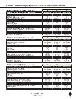
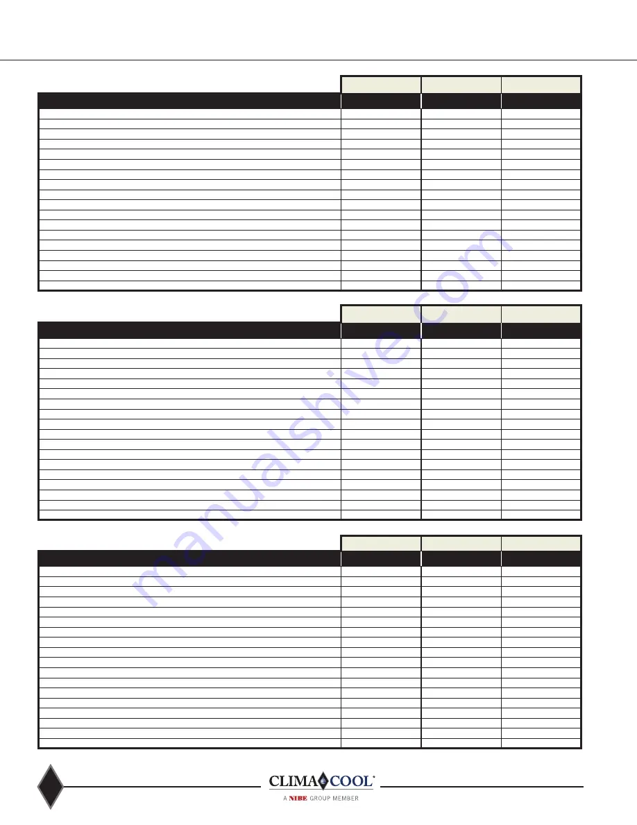
Remote Condenser Physical Data: 30°F TD & 110°F Maximum Ambient
Remote Condenser “H” Series
Model UCR
30
50
70
Model RC (1140 RPM / 30°F TD / 110°F Max Ambient)
RC1-008A*H20
RC2-026A*H48
RC2-031A*H48
Quantity of Remote Condensers Needed
2
1
1
Heat Exchanger (Remote Air-Cooled Type)
Alum. fin/cu tube
Alum. fin/cu tube
Alum. fin/cu tube
Fins per Inch (FPI)
10
8
8
Independent Refrigerant Circuits (Quantity)
1
2
2
Fan Motor Drive Type I Fan Dia. (in.)
Direct I 26”
Direct I 30”
Direct I 30”
Total CFM
12,900
39,600
38,100
Fan Speed
1140
1140
1140
Fan Motor Hp (ea)
1/3 hp
1.5 hp
1.5 hp
Quantity of Fan Motors
2
4
4
kW Input (ea.) Fan Motor I Total kW Input for All Motors
1.2 I 2.4
1.93 I 7.7
1.93 I 7.7
FLA per Fan Motor @ 460V-3-60 I Total FLA @ 460V-3-60
1.3 I 2.6
3.5 I 14
3.5 I 14
Total Heat Rejection @ 1°F TD I THR @ 30°F TD (MBH)
8.0 I 240
26.2 I 786
31.4 I 942
Max. Design Working Pressure - Ref. side I Test Pressure (Psig.)
600 I 650
600 I 650
600 I 650
Condenser Refrigerant Inlet Connection; Qty. @ Size O.D. (Inches)
1 @ 1-3/8”
2 @ 1-3/8”
2 @ 1-5/8”
Condenser Refrigerant Outlet Connection; Qty. @ Size O.D. (Inches)
1 @ 1-1/8”
2 @ 1-3/8”
2 @ 1-3/8”
Sound Level (dB @ 10’)
74.5
78.4
78.4
Dimensions: W x L x H (Inches)
43 X 97 X 40.5
88 X 127 X 49
88 X 127 X 49
Net Weight I Shipping Weight (lbs)
530 I 680
1340 I 1520
1440 I 1620
Remote Condenser “X” Series
Model UCR
30
50
70
Model RC (830 RPM / 30°F TD / 110°F Max. Ambient)
RC2-018A*X48
RC2-026A*X40
RC2-032A*X44
Quantity of Remote Condensers Needed
1
1
1
Heat Exchanger (Remote Air-Cooled Type)
Alum. fin/cu tube
Alum. fin/cu tube
Alum. fin/cu tube
Fins per Inch (FPI)
8
10
14
Independent Refrigerant Circuits (Quantity)
2
2
2
Fan Motor Drive Type I Fan Dia. (in.)
Direct I 30”
Direct I 30”
Direct I 30”
Total CFM
31,700
30,500
29,300
Fan Speed
830
830
830
Fan Motor Hp (ea)
1.0 hp
1.0 hp
1.0 hp
Quantity of Fan Motors
4
4
4
kW Input (ea.) Fan Motor I Total kW Input for All Motors
1.1 I 4.4
1.1 I 4.4
1.1 I 4.4
FLA per Fan Motor @ 460V-3-60 I Total FLA @ 460V-3-60
2.4 I 9.6
2.4 I 9.6
2.4 I 9.6
Total Heat Rejection @ 1°F TD I THR @ 30°F TD (MBH)
17.5 I 525
26.2 I 786
32.0 I 960
Max. Design Working Pressure - Ref. side I Test Pressure (Psig.)
600 I 650
600 I 650
600 I 650
Condenser Refrigerant Inlet Connection; Qty. @ Size O.D. (Inches)
2 @ 1-3/8”
2 @ 1-3/8”
2 @ 1-5/8”
Condenser Refrigerant Outlet Connection; Qty. @ Size O.D. (Inches)
2 @ 1-1/8”
2 @ 1-3/8”
2 @ 1-5/8”
Sound Level (dB @ 10’)
66.9
66.9
66.9
Dimensions: W x L x H (Inches)
88 X 127 X 49
88 X 127 X 49
88 X 127 X 49
Net Weight I Shipping Weight (lbs)
1240 I 1420
1340 I 1520
1440 I 1620
Remote Condenser “Q” Series
Model UCR
30
50
70
Model RC (540 RPM / 30°FTD / 110°F Max. Ambient)
RC2-017A*Q42
RC2-025A*Q44
RC2-032A*Q62
Quantity of Remote Condensers Needed
1
1
1
Heat Exchanger (Remote Air-Cooled Type)
Alum. fin/cu tube
Alum. fin/cu tube
Alum. fin/cu tube
Fins per Inch (FPI)
12
14
12
Independent Refrigerant Circuits (Quantity)
2
2
2
Fan Motor Drive Type I Fan Dia. (in.)
Direct I 30”
Direct I 30”
Direct I 30”
Total CFM
22,300
20,800
32,300
Fan Speed
540
540
540
Fan Motor Hp (ea)
1/2 hp
1/2 hp
1/2 hp
Quantity of Fan Motors
4
4
6
kW Input (ea.) Fan Motor I Total kW Input for All Motors
0.43 I 1.72
0.43 I 1.72
0.43 I 1.72
FLA per Fan Motor @ 460V-3-60 I Total FLA @ 460V-3-60
1.75 I 7.0
1.75 I 7.0
1.75 I 10.5
Total Heat Rejection @ 1°F TD I THR @ 30°F TD (MBH)
17.3 I 519
24.5 I 735
32.4 I 972
Max. Design Working Pressure - Ref. side I Test Pressure (Psig.)
600 I 650
600 I 650
600 I 650
Condenser Refrigerant Inlet Connection; Qty. @ Size O.D. (Inches)
2 @ 1-3/8”
2 @ 1-3/8”
2 @ 1-5/8”
Condenser Refrigerant Outlet Connection; Qty. @ Size O.D. (Inches)
2 @ 1-1/8”
2 @ 1-3/8”
2 @ 1-5/8”
Sound Level (dB @ 10’)
55.7
55.7
57.3
Dimensions: W x L x H (Inches)
88 X 127 X 49
88 X 127 X 49
88 X 180 X 49
Net Weight I Shipping Weight (lbs)
1240 I 1420
1440 I 1620
1990 I 2230
Summary of Contents for CLIMACOOL UCR 30
Page 19: ...17 www climacoolcorp com Voltage Phase Monitor Wiring Diagram...
Page 29: ...27 www climacoolcorp com Evaporator Water Pressure Drop Charts...
Page 30: ...28 www climacoolcorp com Glycol Performance Adjustments Factor Charts...
Page 78: ...76 www climacoolcorp com Wiring Diagram...
Page 79: ...77 www climacoolcorp com Wiring Diagram...
Page 80: ...78 www climacoolcorp com Wiring Diagram CoolLogic Control Panel...
Page 81: ...79 www climacoolcorp com Wiring Diagram CoolLogic Control Panel...


