


14
G e o t h e r m a l H e a t i n g a n d Co o l i n g
Tranquility
®
22 Digital (TZ
)
Series - 60Hz
R e v. : N o v e m b e r 1 8 , 2 0 2 2
Flushing the Earth Loop
⚠
WARNING!
⚠
WARNING!
Disconnect electrical power source to prevent
injury or death from electrical shock.
Once piping is completed between the unit and the ground
loop, final purging and charging of the loop is needed.
A flush cart (at least a 1.5 hp [1.1 kW] pump) is needed to
achieve adequate flow velocity in the loop to purge air and
dirt particles from the loop itself. Antifreeze solution is used
in most areas to prevent freezing. All air and debris must be
removed from the earth loop piping system before operation,
Flush the loop with a high volume of water at a high velocity
(2 fps [0.6 m/s] in all piping),
using a filter in the loop return
line, of the flush cart to eliminate debris from the loop system.
See Table 1 for flow rate required to attain 2 fps [0.6 m/s]. The
steps below must be followed for proper flushing.
Table 1: Minimum Flow Required to Achieve 2 ft/sec variety
PE Pipe Size
Flow (GPM)
3/4"
4 [4.3 L/M per KW]
1"
6 [6.5 L/M per KW]
1 1/4"
10 [10.8 L/M per KW]
1 1/2"
13 [14.0 L/M per KW]
2"
21 [22.6 L/M per KW]
Units with internal variable speed pumps also include a
check valve internal to the pump. It is not possible to flush
backwards through this pump. Care must be taken to
connect the flush cart hoses so that the flush cart discharge
is connected to the “water in” flushing valve of the heat
pump.
LOOP FILL
Fill loop (valve position A, see Figure 15a) with water from a
garden hose through flush cart before using flush cart pump
to ensure an even fill and increase flushing speed. When
water consistently returns back to the flush reservoir, switch
to valve position B (figure 15b).
Isolate expansion tank for flushing procedure using the ball
valve. During dead heading of flush cart pump, isolation will
prevent compression of bladder in the expansion tank and
flush cart fluid level dropping below available capacity.
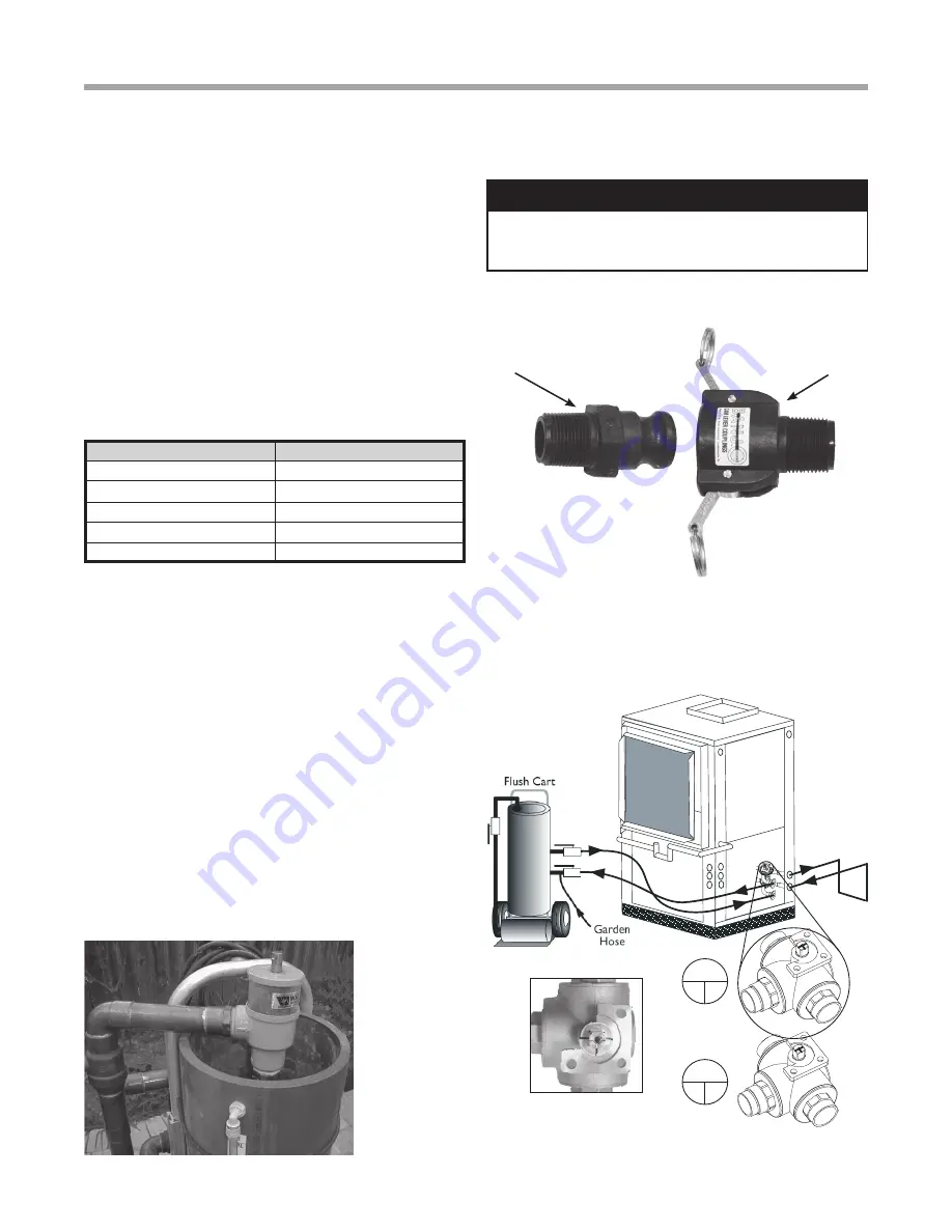
Figure 14a: Typical Cleanable Flush
Cart Strainer (100 mesh [0.149 mm])
Figure 14b: Cam Fittings for Flush Cart Hoses
Attach to Flow
Controller Flush Port
Connect to Flush
Cart Hose (1 of 2)
NOTICE: A hydrostatic pressure test is required on ALL
piping, especially underground piping before final backfill
per IGSHPA and the pipe manufacturers recommendations.
Figure 15a: Valve Position A – Loop Fill/Flush
Loop
Out
In
Valve Position
Flush Port
Front of Unit
Valve Position


