


21
c l i m a t e m a s t e r.c o m
Tranquility
®
22 Digital (TZ
)
Series - 60Hz
R e v. : N o v e m b e r 1 8 , 2 0 2 2
Ground Loop Heat Pump Applications, Cont’d.
LOW WATER TEMPERATURE CUTOUT SETTING –
DXM2.5 CONTROL
When antifreeze is selected, the LT1 jumper (JW3) should
be clipped to select the low temperature (antifreeze 10°F
[-12.2°C]) set point and avoid nuisance faults (see “Low
Water Temperature Cutout Selection” in this manual).
⚠
WARNING!
⚠
WARNING!
Always dilute alcohols with water (at least 50%
solution) before using. Alcohol fumes are flammable and
can cause serious injury or death if not handled properly.
When handling methanol (or any alcohol), always wear
eye protection and rubber gloves as alcohols are easily
absorbed through the skin.
-50°F
-40°F -30°F -20°F -10°F
0°F
10°F
20°F
30°F
40°F
50°F
0.960
0.965
0.970
0.975
0.980
0.985
0.990
0.995
1.000
Low Temperature Protection
Specific Gravity
-45.6°C
-40°C
-34.4°C
-28.9°C
-23.3°C
-17.8°C
-12.2°C
-6.7°C
-1.1°C
4.4°C
10°C
1.00
1.01
1.02
1.03
1.04
1.05
1.06
1.07
Low Temperature Protection
Specific Gravity
-40°F
-30°F
-20°F
-10°F
0°F
10°F
20°F
30°F
40°F
-40°C -34.4°C -28.9°C -23.3°C -17.8°C -12.2°C -6.7°C -1.1°C
4.4°C
0.975
0.980
0.985
0.990
0.995
1.000
-5°F
0°F
5°F
10°F
15°F
20°F
25°F
30°F
35°F
1.7°C
-1.1°C
-3.9°C
-6.7°C
-9.4°C
-12.2°C
-15.0°C
-17.8°C
-20.6°C
Low Temperature Protection
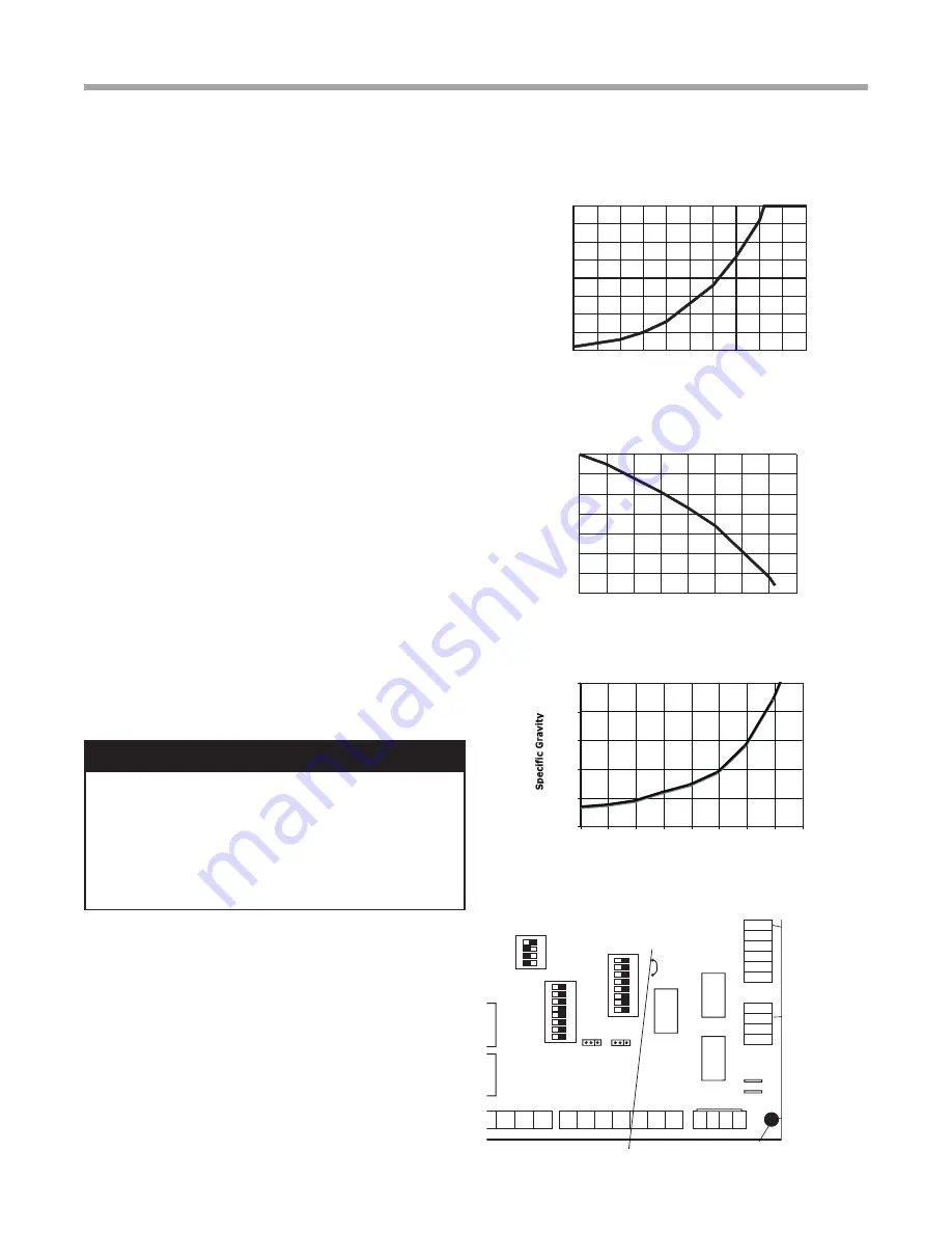
Chart 1a: Methanol Specific Gravity
Chart 1b: Propylene Glycol Specific Gravity
Chart 1c: Ethanol Specific Gravity
Figure 17: Low Temperature Cutout Selection
P1
Alarm
Relay
Comp
Relay
O
Y1
Y2
W
G
C
R
AL1
24Vdc
EH1
EH2
P6
R
C
Off On
JW3
A
OVR
ESD
C
R
NSB
AL2
JW1
Acc1
Relay
Acc2
Relay
H
COM
NC1
NO1
COM
NC2
NO2
P3
CO
RV
RV
LT1
LT1
LT2
LT2
LP
LP
HP
HP
P7
Status
Fault
R
R
CC
CCG
CO
S1
S2
1
12
1
4
Fa
cto
ry
U
se
(240Vac)
Com
N.O.
Fan Enable
5 1/2"
7"
6 1/2"
5"
Use 4 mounting screws
#6 sheet metal screw 1” long
1.5
3/8” standoff
Factory low
voltage Molex
connection for
unit harness
Factory low
voltage Molex
connection for
electric heat
harness
Micro
U1
Off On
P2
COH
COM
AO2
P11
Gnd T1
P10
T2 T2 T3 T3 T4 T4
T5
P9
T5 T6 T6
A0-1 A0-2
Off On
S3
RV
Relay
CCH
Relay
Test
P5
B-
Gnd
P4
A+ 24V
(240Vac)
Fan Speed
N.O.
N.C.
12V
OUT
Gnd
P8
IN
NC
P12
Note: There is only
one T1 connection
1 2 3 4
1 2 3 4 5 6 7 8
1 2 3 4 5 6 7 8
AO1 Gnd
1
DXM2.5 PCB
JW3-LT1 jumper should be clipped for low
temperature operation.
cart noting the color of the discharge fluid. Adding food
coloring to the antifreeze can help indicate where the
antifreeze is in the circuit and prevents the dumping of
antifreeze out the waste port. Repeat if necessary.
5. Be careful when handling methanol (or any alcohol).
Always wear eye protection and rubber gloves. The
fumes are flammable, and care should be taken with all
flammable liquids. Open flush valves to flush through
both the unit and the loop and flush until fluid is
homogenous and mixed. It is recommended to run the
unit in the heating and cooling mode for 15-20 minutes
each to ‘temper’ the fluid temperature and prepare it
for pressurization. Devoting this time to clean up can be
useful. This procedure helps prevent the periodic “flat”
loop condition.
6.
Close the flush cart return valve; and immediately
thereafter, close the flush cart supply valve, leaving
a positive pressure in the loop of approximately 50
psi [345 kPa]. This is a good time to pressure check
the system as well. Check the freeze protection of
the fluid with the proper hydrometer to ensure that
the correct amount of antifreeze has been added to
the system. The hydrometer can be dropped into the
flush reservoir and the reading compared to Chart
1a for Methanol, 1b for Propylene Glycol, and 1c for
Ethanol to indicate the level of freeze protection. Do
not antifreeze more than a +10°F [-12.2°C] freeze
point. Specific gravity hydrometers are available in the
residential price list. Repeat after reopening and flushing
for a minute to ensure good second sample of fluid.
Inadequate antifreeze protection can cause nuisance low
temperature lockouts during cold weather.
7.
Close the flush cart return valve; immediately thereafter,
close the flush cart supply valve, shut off the flush cart
leaving a positive pressure in the loop of approximately
50-75 psi [345-517 kPa]. Refer to Figure 15d for more
details.


