42
G e o t h e r m a l H e a t i n g a n d Co o l i n g
Tranquility
®
22 Digital (TZ
)
Series - 60Hz
R e v. : N o v e m b e r 1 8 , 2 0 2 2
UNIT START-UP PROCEDURE
1.
Turn the thermostat fan position to “ON.” Blower
should start.
2. Turn Blower off.
3. Ensure all valves are adjusted to their full open position.
Ensure line power to the heat pump is on.
4. Room temperature should be within the minimum-
maximum ranges of listed in the unit IOM. During start-
up checks, loop water temperature entering the heat
pump should be between 30°F [-1°C] and 95°F [35°C].
5.
It is recommended that water-to-air units be first
started in the cooling mode, when possible. This will
allow liquid refrigerant to flow through the filter-drier
before entering the TXV, allowing the filter-drier to
catch any debris that might be in the system before it
reaches the TXV.
6. Two factors determine the operating limits of geothermal
heat pumps, (a) return air temperature, and (b) entering
water temperature. When either of the factors is at a
minimum or maximum level, the other factor must be at
normal levels to insure proper unit operation.
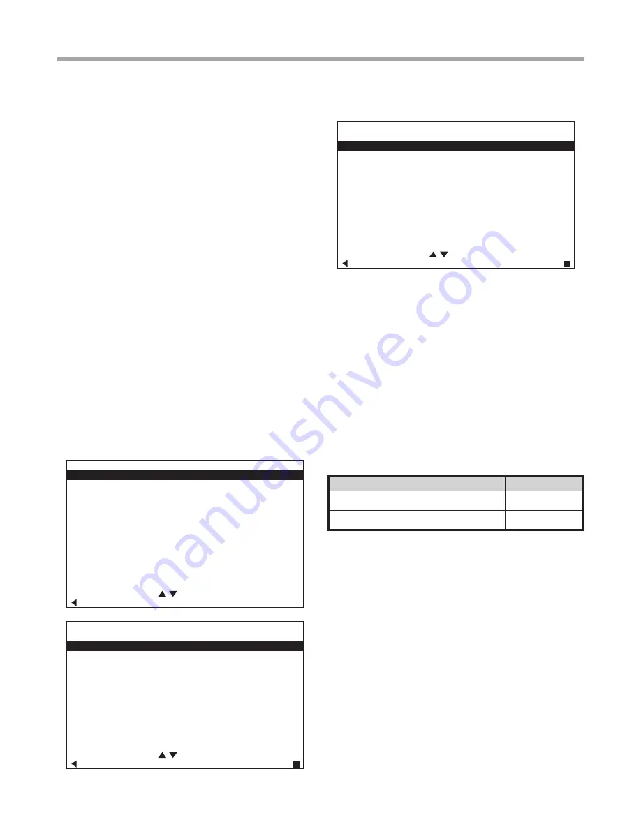
a. Place the unit in Manual Operation. When in
manual mode activate Y1, Y2, and O to initiate the
cooling mode. Also manually increase CFM until
desired cooling CFM is achieved. Next adjust pump
speed % until desired loop temperature difference
(leaving water temperature minus entering water
temperature) is achieved. (For modulating valve
adjust valve %).
INSTALLER SETTINGS
THERMOSTAT CONFIG
SYSTEM CONFIG
ACCESSORY CONFIG
INPUT DEALER INFO
HUMIDITY CONFIG
TEMPERATURE CONTROL
DEMAND REDUCTION CNFG
SERVICE MODE
SETPOINT LIMITS
RESTORE DEFAULTS
DXM2.5 3.3
AWC99U01 C 1.0
SELECT OPTION
PREVIOUS
SERVICE MODE
MANUAL OPERATION
CONTROL DIAGNOSTICS
DIPSWITCH CONFIG
FAULT HISTORY
CLEAR FAULT HISTORY
SELECT OPTION
PREVIOUS SELECT
MANUAL OPERATING MODE
Y1
COMM OUTPUT
OFF
Y2
COMM OUTPUT
OFF
W
COMM OUTPUT
OFF
O
COMM OUTPUT
OFF
G
COMM OUTPUT
OFF
H
COMM OUTPUT
OFF
DH
COMM OUTPUT
OFF
ECM AIRFLOW
0
PUMP SPEED
0%
TEST MODE
OFF
SELECT OPTION
PREVIOUS SELECT
b. Check for cool air delivery at the unit grille within a
few minutes after the unit has begun to operate.
NOTE: Units have a five minute time delay in the control
circuit that can be bypassed on the DXM2.5 control board
by placing the unit in the “Test” mode as shown in the unit
IOM. Check for normal air temperature drop of 15°F to
25°F (cooling mode).
c. Verify that the compressor is on and that the water
temperature rise (cooling mode) is within normal
range.
d. Check the elevation and cleanliness of the
condensate lines. Dripping may be a sign of a
blocked line. Check that the condensate trap is filled
to provide a water seal.
Water Flow, gpm (l/m)
Rise, Cooling °F
For Closed Loop:
Ground Source or Closed
Loop Systems at 3 gpm per ton (3.9 l/m per kw)
9 - 12
For Open Loop:
Ground Water Systems at
1.5 gpm per ton (2.0 l/m per kw)
20 - 26
e. Turn thermostat to “OFF” position. A hissing noise
indicates proper functioning of the reversing valve.
7.
Allow five (5) minutes between tests for pressure to
equalize before beginning heating test.
a. Go into Manual Mode activate Y1, and Y2 for
Heating. Also manually increase CFM until desired
heating CFM is achieved. Next adjust pump
speed % until desired loop temperature difference
(entering water temperature minus leaving water
temperature) is achieved. (For modulating valve
adjust valve %).
b. Check for warm air delivery at the unit grille within a
few minutes after the unit has begun to operate.
NOTE: Units have a five minute time delay in the control
circuit that can be bypassed on the DXM2.5 control board
by placing the unit in the “Test” mode as shown in the unit
IOM. Check for normal air temperature rise of 20°F to 30°F
(heating mode).
Unit Start-Up Procedure


