background image

GB

12

!

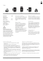
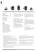
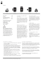
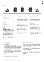
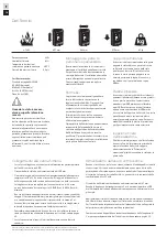
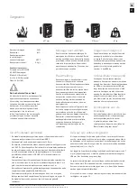
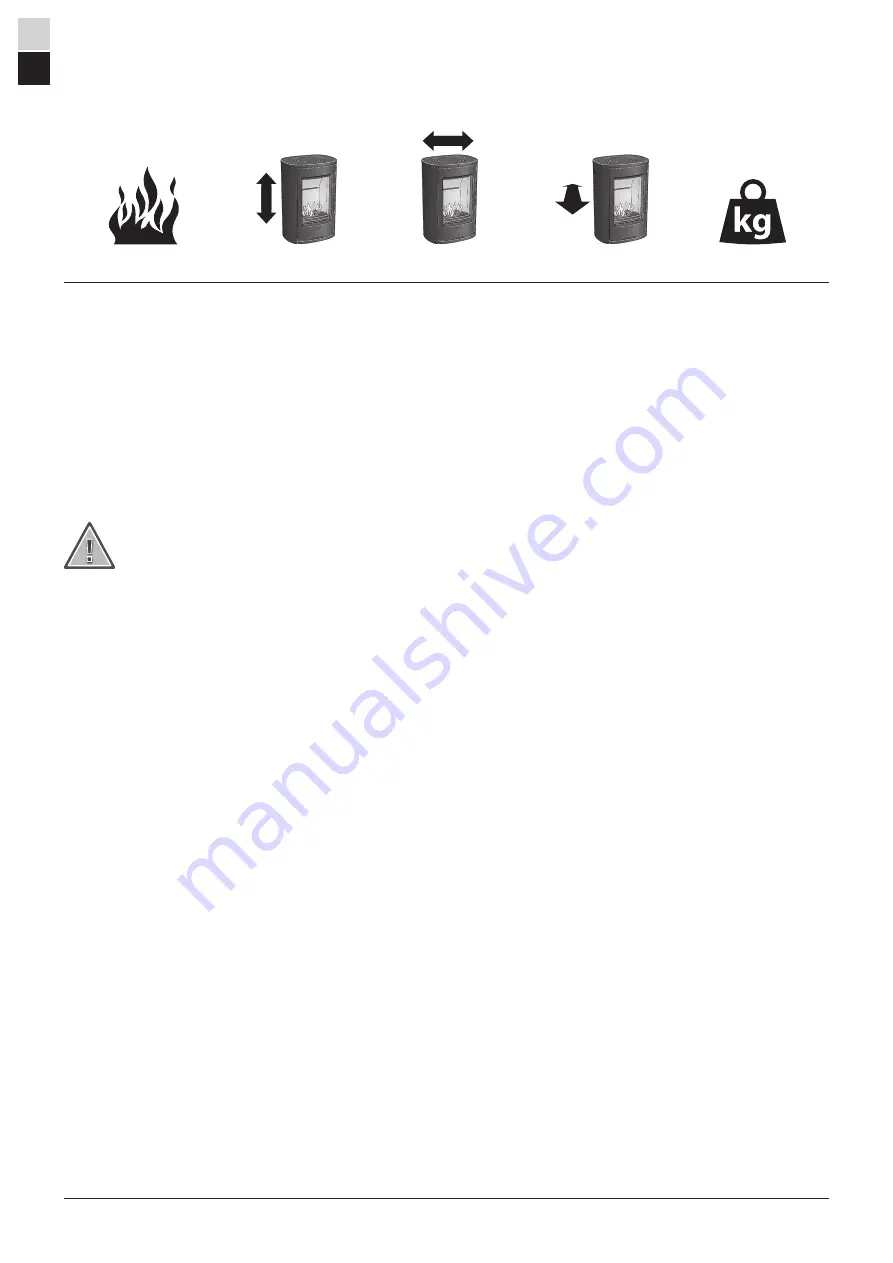
3-7 kW

697 mm

465 mm

379 mm

67 kg

Installation by authorised 
technician 

This manual contains instructions about how 
the stoves must be assembled and installed. 
To ensure the function and safety of the stove, 
we recommend that the installation is carried 
out by an authorised technician. Contact one 
of our dealers who can recommend suitable 
technicians. 

Building application

These main instructions may give guidance 
which would contravene national building 
regulations. Please refer to supplementary 
instructions or ask your local authority for 
advice regarding building regulations.
Before installing a stove or erecting a chimney 
it is necessary for you to make a building 
application permission to your local authority.
The owner of the house is personally 
responsible for ensuring compliance with the 
mandatory safety requirements and must 
have the installation approved by a qualified 
inspector. Your local chimney sweep must 
also be informed about the installation as this 
will affect the routines for regular chimney-
sweeping services.

Structural support

Check that the wood joists are strong enough 
to bear the weight of the stove and chimney. 
The stove and chimney can usually be placed 
on a normal wooden joist in a single occupancy 
house if the total weight does not exceed
400 kg.

Hearth plate

Due to the risk of falling embers, a flammable 
floor must be protected by a hearth plate. It 
must extend 300 mm in front of the stove and 
100 mm on each side of the stove, or have a 
200 mm extension on each side of the opening. 
The hearth plate can consist of natural stone, 
concrete, metal plate or glass. A glass hearth 
plate is available as an accessory for these 
models.

Final inspection of the 
installation

It is extremely important that the installation 
is inspected by an authorised chimney sweep 
before the stove is used. Also read the 
”Lighting instructions”, before lighting for the 
first time. 

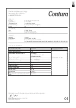
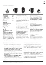
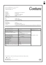
Nominal effect 

5 kW

Efficiency 

81 %

Flue gas temperature in the
connection at nominal output 

309°C

Flue gas mass flow 

4,3 g/s

Type approved in accordance with:

European standard EN-13240
NS 3059 (Norway)
BImSchV.2 (Germany)
Art. 15a B-VG (Austria)
Clean Air Act. (UK)

The stove becomes very hot

During operation, certain surfaces of the 
stove become very hot and can cause 
burn injury if touched. Be aware of the 
strong heat radiated through the hatch 
glass. Placing flammable material closer 
than the safe distance indicated may 
cause a fire. Pyre lighting can cause quick 
gas ignition with the risk of damage to 
property and personal injury. 

Connection to chimney

•  The stove must be connected to chimneys dimensioned for a minimum flue 

gas temperature of 400°C. 

•  The external diameter of the connection sleeve is 150 mm. 
•  Normal chimney draw under nominal operation should be between 20-25 

Pa close to the connector. The draft is affected both by the length and 
area of the chimney, and by how well sealed it is. Minimum recommended 
chimney length is 3.5 m and suitable cross section area is 150-200 cm² 
(140-160 mm in diameter). 

•  A flue with sharp bends and horizontal routing reduces the draught in 

the chimney. Maximum horizontal flue is 1 m, on the condition that the 
vertical flue length is at least 5 m. 

•  It must be possible to sweep the full length of the flue and the soot 

hatches must be easily accessible.

•  Carefully check that the chimney is sealed and that there is no leakage 

around soot hatches and flue connections. See page 25.

•  The stove meets the requirements for connection to a branched flue pipe.

Supply of combustion air

When a stove is installed in a room, the demand for air supply to the room 
increases. Air can be provided indirectly via a vent in the outer wall or via a 
duct from the outside that is connected to the connector on the underneath 
of the stove. The amount of air needed for combustion is 15 m

3

/h.

The connector for the combustion air has an external diameter of 67 mm. 
When duct routing further than 1 m the pipe diameter must be increased to 
100 mm and a correspondingly larger wall vent must be selected. 

In hot areas, the duct should be insulated with 30 mm mineral wool with a 
moisture inhibiting outer cover. It is also important to seal around the hole 
in the wall (or floor) of the lead-in using sealant.

A 1 m length of condensation insulated ducting for combustion air is 
available as an accessory. See page 25.

Facts

Contura reserves the right to change dimensions and procedures described in these instructions 
at any time without special notice. The current edition can be downloaded from www.contura.eu

Summary of Contents for Contura C810W Style

Page 1: ...C810W Style contura eu ...

Page 2: ...tances 13 Distanze di sicurrezza 19 Installasjonsavstand 7 Installationsafstand 16 Installatieafstand 22 Prestandadeklaration 5 Déclaration des performance 11 Declaration of performance 14 Dichiarazione di prestazione 20 Ytelseserklæring 8 Præstationserklæring 17 Prestatieverklaring 23 Montering 24 Montage 24 Assembly 24 Montaggio 24 Montering 24 Montering 24 Monteren 24 ...

Page 3: ...or vid beröring Var också uppmärksam på den kraftiga värmestrålningen genom luckglaset Om brännbart material placeras närmare än angivet säkerhetsavstånd kan brand förorsakas Pyreldning kan orsaka hastig gasantändning med risk för både materiella skador och personskador som följd Anslutning till skorsten Kaminen ska anslutas till skorsten dimensionerad för minst 400 C rökgastemperatur Anslutningss...

Page 4: ...öppningen till brännbar byggnadsdel eller inredning ska vara 1 1 m E minsta höjd till lutande tak vid centrum av skorsten Installationsavstånd 465 Min 300 697 Min 1000 Brännbart tak 106 563 59 380 Utv Ø150 Tilluftsstos Ø67 Tillåtet område för brännbar byggnadsdel 582 350 100 196 11 380 250 350 Brandmur Brännbar vägg 430 800 1100 196 380 11 200 Brandmur INSTALLATION MOT BRÄNNBAR VÄGG INSTALLATION M...

Page 5: ... 305 2011 Nr C810W CPR 190423 SE 0 DEKLARERAD PRESTANDA Väsentliga egenskaper Prestanda Harmoniserad teknisk specifikation Reaktion vid brandpåverkan A1 WT Minsta avstånd till brännbart material Sida 350 mm Övriga säkerhetsavstånd enligt installationsanvisningen Risk för utfallande glöd Klarar EN 13240 2001 A2 2004 Emissioner från förbränningen CO 0 12 0 09 Yttemperaturer Klarar Rengöringsmöjlighe...

Page 6: ...pmerksom på den kraftige varmestrålingen gjennom glasset Hvis det plasseres brennbart materiale nærmere enn den angitte sikkerhetsavstanden kan det forårsake brann Ulmefyring kan medføre eksplosjonsartig antennelse av røykgassene med fare for både materielle skader og personskader Tilkobling til skorstein Ovnen skal kobles til en skorstein som er dimensjonert for en røykgasstemperatur på minst 400...

Page 7: ...l For å unngå misfarging på malt brannmur anbefaler vi samme sideavstand som til brennbar vegg INSTALLASJON MOT BRENNBAR VEGG INSTALLASJON MOT BRANNMUR C810W Style 465 Min 300 697 Min 1000 Brennbart tak 106 563 59 380 Ø150 Tilkobling til forbrenningsluft Ø67 582 350 100 196 11 380 250 350 Brennbar vegg Brannmur av tegl eller betong 430 800 1100 196 380 11 200 Brannmur av tegl eller betong E 630 Mi...

Page 8: ...g EU 305 2011 Nr C810W CPR 190423 SE 0 ERKLÆRT YTELSE Viktige egenskaper Ytelse Harmonisert teknisk spesifikasjon Reaksjon ved brannpåvirkning A1 WT Minste avstand til brennbart materiale Side 350 mm Øvrige sikkerhetsavstander ifølge installasjonsveiledningen Fare for utfallende glør Ytelse EN 13240 2001 A2 2004 Utslipp fra forbrenningen CO 0 12 0 09 Overflatetemperaturer Ytelse Rengjøringsmulighe...

Page 9: ...yonne par la vitre du poêle Éloignez les matériaux inflammables à la distance de sécurité prescrite Si on laisse couver le feu on risque de provoquer une inflammation rapide de gaz susceptible d être à l origine de blessures et de dégâts matériels Raccordement à la cheminée Le poêle doit être raccordé à une cheminée dimensionnée pour une température des gaz de fumée de 400 C Le diamètre extérieur ...

Page 10: ...écolorer la peinture de la cloison ininflammable nous recommandons de respecter les mêmes distances latérales que pour un mur inflammable INSTALLATION CONTRE UNE CLOISON ININFLAMMABLE INSTALLATION CONTRE UN MUR PARE FEU C810W Style 465 Min 300 697 Min 1000 Plafond inflammable 106 563 59 380 Ø150 Manchon d arrivée d air Ø67 582 350 100 196 11 380 250 350 Cloison inflammable Mur pare feu en birque o...

Page 11: ...mément au règlement UE 305 2011 N C810W CPR 190423 SE 0 PERFORMANCES DÉCLARÉES Caractéristiques essentielles Performances Spécifications techniques harmonisées Réaction au feu A1 WT Distance minimale à respecter par rapport aux matériaux combustibles adjacents Latérale 350 mm Autres distance de sécurité selon les instructions d installation Risque de projections de braises Assure EN 13240 2001 A2 ...

Page 12: ... The stove becomes very hot During operation certain surfaces of the stove become very hot and can cause burn injury if touched Be aware of the strong heat radiated through the hatch glass Placing flammable material closer than the safe distance indicated may cause a fire Pyre lighting can cause quick gas ignition with the risk of damage to property and personal injury Connection to chimney The st...

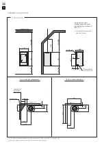
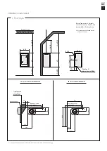
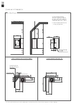
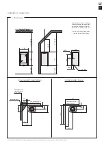
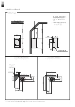
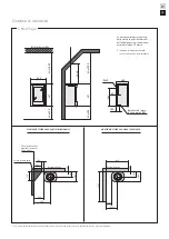
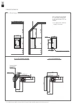
Page 13: ...lding To prevent discolouration of painted non flammable walls we recommend that the same side distance as to combustible walls is used INSTALLATION AGAINST COMBUSTIBLE WALLS INSTALLATION AGAINST FIREWALLS C810W Style 465 Min 300 697 Min 1000 Combustible roof 106 563 59 380 Ø150 Air inlet Ø67 582 350 100 196 11 380 250 350 Combustible wall Fire retardant wall of brick or concrete 430 800 1100 196 ...

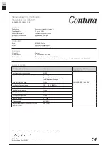
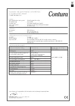
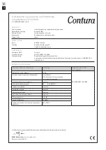
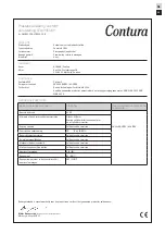
Page 14: ... Regulation EU 305 2011 No C810W CPR 190423 SE 0 DECLARED PERFORMANCE Essential characteristics Performance Harmonised technical specification Reaction to fire A1 WT Minimum distance to combustible material Side 350 mm Other safety distances according to the installation instructions Risk of falling embers Pass EN 13240 2001 A2 2004 Emissions from combustion CO 0 12 0 09 Surface temperatures Pass ...

Page 15: ...meudstråling gennem lågeglasset Hvis der anbringes brændbart materiale nærmere end den angivne sikkerhedsafstand kan det medføre brand Hvis brændet kun ulmer kan det forårsage en eksplosionsagtig antændelse af røggasserne med risiko for såvel materielle skader som personskader Tilslutning til skorsten Brændeovnen skal tilsluttes en skorsten der er dimensioneret til mindst 400 C røggastemperatur Ti...

Page 16: ...r bygningsdel INSTALLATION MOD BRÆNDBAR VÆG INSTALLATION MOD BRANDMUR For at undgå misfarvning af malede ikke brændbare vægge anbefaler vi den samme sideafstand som til brændbare vægge C810W Style 465 Min 300 697 Min 1000 Brændbart loft 106 563 59 380 Ø150 Friskluftsstuds Ø67 582 350 100 196 11 380 250 350 Brændbar væg Brandsikker væg 430 800 1100 196 380 11 200 Brandsikker væg E 630 Min 300 697 M...

Page 17: ...305 2011 Nr C810W CPR 190423 SE 0 ERKLÆRET PRÆSTATION Væsentlige egenskaber Præstation Harmoniseret teknisk specifikation Reaktion ved brandpåvirkning A1 WT Mindste afstand til brændbart materiale Side 350 mm Øvrige sikkerhedsafstande i henhold til monteringsvejledningen Risiko for at gløder falder ud Klarer EN 13240 2001 A2 2004 Emissioner fra forbrændingen CO 0 12 0 09 Overfladetemperaturer Klar...

Page 18: ...are inoltre attenzione al forte calore irradiato dal vetro dello sportello La presenza di materiale infiammabile ad una distanza inferiore a quella di sicurezza indicata potrebbe provocare un incendio Bruciare un quantitativo eccessivo di legna può provocare la rapida emissione di gas infiammabili con il rischio di danni a cose e persone Collegamento alla canna fumaria La stufa va collegata a una ...

Page 19: ...mmabili MONTAGGIO VICINO A UNA PARETE INFIAMMABILE MONTAGGIO VICINO A UN MURO TAGLIAFUOCO Per evitare deterioramenti delle pareti ignifughe dipinte si consiglia di mantenere la stessa distanza indicata per le pareti infiammabili C810W Style 465 Min 300 697 Min 1000 Tetto infiammabile 106 563 59 380 Ø150 Bocchetta di presa d aria esterna Ø67 582 350 100 196 11 380 250 350 Parete infiammabile Parete...

Page 20: ... regolamento UE 305 2011 N C810W CPR 190423 SE 0 PRESTAZIONI DICHIARATE Caratteristiche fondamentali Prestazioni Specifiche tecniche armonizzate Reazione in caso di incendio A1 WT Distanza minima al materiale infiammabile Lato 350 mm Altre distanze di sicurezza secondo le istruzioni di montaggio Rischio di caduta di braci ardenti Superato EN 13240 2001 A2 2004 Emissioni dalla combustione CO 0 12 0...

Page 21: ...eer heet Als de kachel in bedrijf is worden bepaalde oppervlakken zeer heet en kunnen deze bij aanraking brandwonden veroorzaken Let ook op de sterke warmtestraling door het deurglas Als brandbaar materiaal binnen de vermelde veiligheidsafstand wordt geplaatst kan dit tot brand leiden Smeulend hout kan tot een snelle gasontbranding en daardoor materiële schade en persoonlijk letsel leiden Op schoo...

Page 22: ...LLATIE OP EEN BRANDBARE WAND INSTALLATIE OP BRANDMUUR Om verkleuring van geschilderde onbrandbare wanden te voorkomen bevelen wij dezelfde zijafstand aan als voor brandbare wanden C810W Style 465 Min 300 697 Min 1000 Brandbaar plafond 106 563 59 380 Ø150 Toevoerluchtaansluiting Ø67 582 350 100 196 11 380 250 350 Brandbare muur Brandmuur van steen of beton 430 800 1100 196 380 11 200 Brandmuur van ...

Page 23: ...ijke eigenschappen Prestaties Geharmoniseerde technische specificatie Reactie bij brand A1 WT Minimale afstand tot brandbare materialen Zijkant 350 mm Overige veiligheidsafstanden conform de installatie instructies Kans op vonken Voldoet aan de vereisten EN 13240 2001 A2 2004 Emissies van verbranding CO 0 12 0 09 Oppervlaktetemperaturen Voldoet aan de vereisten Reinigingsmogelijkheden Voldoet aan ...

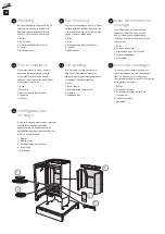
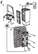
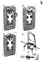
Page 24: ...down to be moved loose components should be removed Removal of the hearth cladding is described at the end of these installation instructions 1 Grille 2 Grate disc 3 Hearth cladding Vermiculite 4 Type plate 5 Fire bars Før opstilling Hvis indsatsen skal lægges ned for at blive flyttet bør løsdele afmonteres Afmontering af ovnbeklædning beskrives i slutningen af denne vejledning 1 Gitter 2 Rund ask...

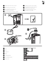
Page 25: ...ière à une cheminée de maçonnerie Rear connection to a masonry chimney Tilslutning bagud til muret skorsten Collegamento alla canna fumaria in muratura dal retro della stufa Achterwaartse aansluiting op een gemetselde schoorsteen SE NO FR GB DK IT NL Tilluft Tilluft Arrivée d air Supply Forbrændingsluft Alimentazione dell aria Toevoerlucht ...

Page 26: ...26 2 1 x2 x2 Ø 8 mm 3 29 ...

Page 27: ...27 4 5 7 60 mm 6 30 ...

Page 28: ...28 8 9 ...

Page 29: ...29 10 11 x4 12 ...

Page 30: ...30 13 14 ...

Page 31: ...31 x2 16 18 mm 15 ...

Page 32: ...ouillage situé sur le côté gauche du poêle The door can be secured in the open position using the locking lever on the left side of the stove Installation of the door Spærring af lågen Lågen kan spærres i åben position ved hjælp af låsearmen på venstre side af brændeovnen Lo sportello può essere bloccato in posizione aperta con una levetta di blocco posta sotto la parte sinistra della stufa Blocca...

Page 33: ...dstedsbekledningen Vermikulitt Voici comment démonter l habillage du foyer Vermiculite How to remove the hearth surround Vermiculite Sådan afmonterer du ovnbeklædningen Vermiculite Come smontare il rivestimento del focolare vermiculite Zo demonteert u de kachelbekleding vermiculiet Handle with care ...

Page 34: ...34 1 2 1 2 5 7 9 6 8 1 2 ...

Page 35: ...35 1 2 12 11 10 ...

Page 36: ...811437 IAV SE EX C810W Style 0 2020 02 06 NIBE AB Box 134 285 23 Markaryd Sweden www contura eu ...

Reviews: