- 10 -
Power supply
The heater is connected to the 3x 230 V (400 V)/50 Hz power grid using a fixed moving cable in which a circuit
breaker (and possibly a current protector) is fitted. The 5 x 2.5 mm² cable must be tripped with a circuit
breaker of appropriate parameters listed in the table (Table 1).
Control power supply
Control inputs RS1, RS2, RS3 are connected to the mains 1 x 230 V/50 Hz with a cable.
Power supply to the inputs via one identical L phase.
It is recommended to trip the control voltage with a 500 mA (0.5 A) fuse.
Fault signaling (fuse blowing)
The contact of the S1/S2 terminal is rated at 5 A/250 VAC.
Switching contact (NO), potential-free.
It is recommended to trip with fuse 1A.
Instructions for connecting wires to terminals:
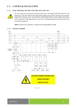
Wires are connected to the Wago terminals on the PCB. The tool to use is a flat head screwdriver of the
appropriate width. The wires are connected from the side (Figure 6). Use appropriate clamping force.
Figure 6
2.3
HEATING UNIT OPERATION
Water temperature control is operated (performed) automatically by an external controller which controls
the heating.
2.4
INSPECTION, MAINTENANCE
Maintenance involves decalcification of the heating element in certain time intervals selected by water
hardness at the place of use.
Damage to the heating element due to calcareous sediments is not accepted
by the manufacturer as a reason for complaint.
Notice:
If the heating unit is used in an accumulation heater, the wear of the anode rod of the
heater may deteriorate. We recommend checking it more frequently. Consider the instructions
of the manufacturer regarding the exchange of the anode rod.


