- 9 -
2.2.3
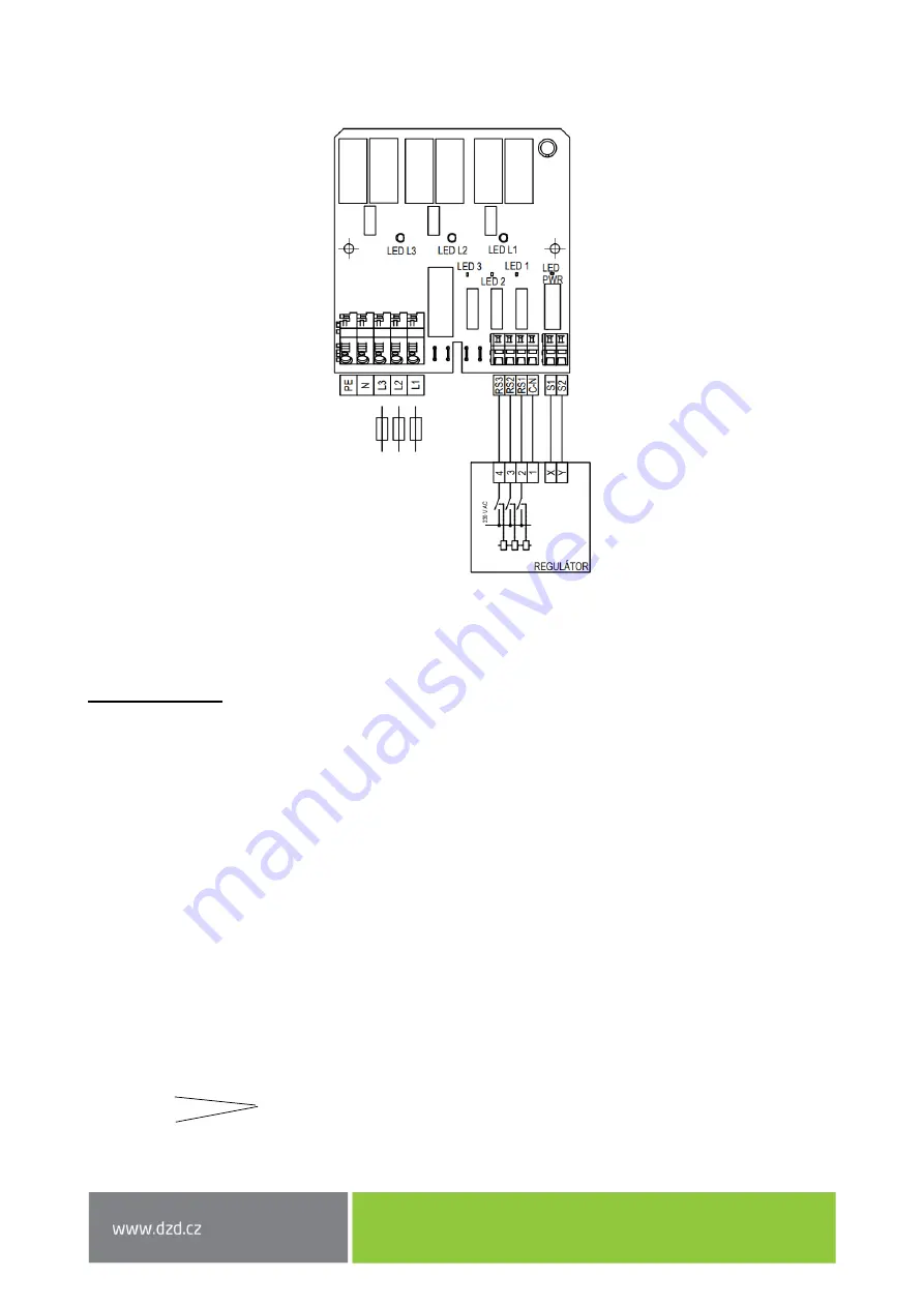
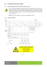
APPLICATION DIAGRAM:
Model design of possible control
Figure 5
2.2.4
WIRING DESCRIPTION
Terminals on PCB
1)
Power supply 400 VAC
PE
–
earth (yellow/green wire)
N
–
working zero (blue wire)
L1
–
phase 1. (brown wire)
L2
–
phase 2. (black wire)
L3
–
phase 3 (grey wire)
Conductor max.
S= 4 mm²
2)
Control, external 230 VAC
RS1
–
control switching L1, switches on heating stage I
RS2
–
control switching L2, switches on heating stage II.
RS3
–
control switching L3, switches on heating stage III.
C_N
–
working zero
Conductor max.
S = 2,5 mm²
3)
Fault signalling (fuse opening), 1 contact
S1
S2
Conductor
max. S = 2,5 mm²
Contact (potential-free)


