background image

Recovery

Leave the disposal of the packaging to the in-
staller who installed the product or to special
waste stations.

When disposing of the product, its constituent
materials and components, e.g. compressors,

fans, circulation pumps and circuit boards, must be dis-
posed of at a special waste station or dealer who
provides this type of service.

To access the separate components, refer to the section
that shows the construction of the product. No special
tools are required for access.

Improper disposal of the product by the user results in
administrative penalties in accordance with current le-
gislation.

5

Chapter 1 | Important information

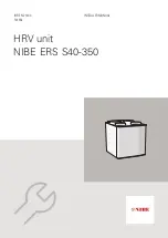
NIBE ERS S40-350

Summary of Contents for ERS S40-350

Page 1: ...IHB EN 2143 3 531854 INSTALLER MANUAL HRV unit NIBE ERS S40 350 UN...

Page 2: ......

Page 3: ...eral ventilation connections 14 Ventilation flow 14 Adjusting ventilation 15 Dimensions and ventilation connections 16 5 Electrical connection 16 Supply 16 Connecting to main product 18 6 Commissionin...

Page 4: ...ce shall not be made by children without supervision Rights to make any design or technical modifications are reserved NIBE 2020 SYMBOLS NOTE This symbol indicates danger to person or ma chine Caution...

Page 5: ...ps and circuit boards must be dis posed of at a special waste station or dealer who provides this type of service To access the separate components refer to the section that shows the construction of...

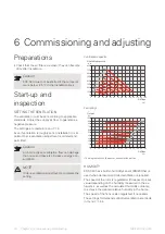
Page 6: ...missioned The inspection must be carried out by a suitably qualified person In addition fill in the page for the installation data in the User Manual Date Signa ture Notes Description Electricity page...

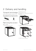
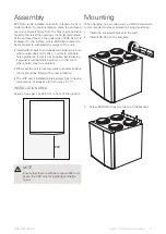
Page 7: ...e covers FRONT COVER 1 Pull the hatch towards yourself INNER FRONT COVER The inner front cover must be removed to access the internal parts 1 Remove the air filters 2 Loosen the screws that hold the i...

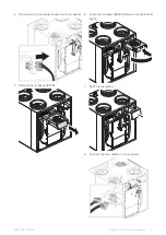
Page 8: ...sion if necessary which means that exhaust air and supply air are connected to the right Extract air Outdoor air Supply air Exhaust air CONVERSION TO RIGHT HANDED VERSION 1 Remove the insulation locat...

Page 9: ...ocated in the re heater 5 Remove the re heater EB18 6 Install the re heater EB18 furthest in the right hand space 7 Refit the insulation 8 Connect the two cables to the re heater 9 Chapter 2 Delivery...

Page 10: ...plug and sensor BT21 furthest in the left hand section 12 Refit the grating 13 Switch the filters around Filter ePM1 55 must be placed on the supply air side 14 Fit the filter cassettes 15 Mark the c...

Page 11: ...lacing it against a wall behind a bedroom or other room where noise may be a problem Wherever the unit is located walls to sound sensitive rooms should be fitted with sound insulation The HRV unit s i...

Page 12: ...GQ3 XL33 XL31 XL32 XL34 AA33 GQ2 EP29 HQ10 HQ11 W500 W119 PZ1 BT21 BT23 BT22 BT20 EB18 MA3 BM20 X1 FQ10 PZ4 NIBE ERS S40 350 Chapter 3 Design of the HRV unit 12 3 Design of the HRV unit...

Page 13: ...BT22 Temperature sensor outdoor air BT23 Electrical components AJBboard AA33 Re heater EB18 Temperature limiter FQ10 Motor for the heat exchanger MA3 Communication cable W119 Cord with connection plug...

Page 14: ...oor air NOTE To ensure a sealed connection to ERS S40 the supplied hose clips must be used for connect ing the air ducts EXHAUST AIR DUCT KITCHEN FAN Exhaust air duct kitchen fan must not be connected...

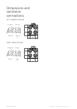
Page 15: ...0 4 x 200 4 x 160 130 130 280 200 145 625 340 Supply air Exhaust air Extract air Outdoor air RIGHT HAND VERSION 600 35 600 4 x 200 4 x 160 130 130 280 200 145 625 340 Extract air Outdoor air Supply ai...

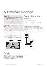
Page 16: ...xample EKKX LiYY or equivalent For electrical wiring diagram see page 27 AA33 S3 AA33 X24 Supply ERS S40 is connected to a earthed single phase wall socket or a permanent installation For permanent in...

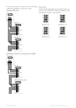
Page 17: ...nd another accessory from NIBE B A GND 12V AA2 X30 1 2 3 4 AA33 X24 AA5 X24 1 2 3 4 5 6 7 8 ISO_12v A B B ISO_GND ISO_GND ISO_12V A A B GND A B GND 1 2 3 4 5 6 7 8 ERS S40 Main product Other accessory...

Page 18: ...30 40 50 60 80 100 70 90 110 120 130 140 100 200 300 400 500 600 700 800 Tillg ngligt tryck Pa Luftfl de l s 30 100 80 60 40 50 70 90 Available pressure Airflow Fan rating1 0 0 10 20 30 40 50 60 70 80...

Page 19: ...range 5 120 min Temp for end of defrosting Setting range 10 0 10 0 C Physical configuration Left means that exhaust air and supply air are connected to the left in the product Changing the configurat...

Page 20: ...d in order for cooling recovery to start Menu 1 2 1 Fan speed Alternatives normal and speed 1 speed 4 The ventilation in the accommodation can be temporarily increased or reduced here When you have se...

Page 21: ...ive on off Highest fan speed Setting range 1 100 Lowest fan speed Setting range 1 100 Time interv change of fan speed Setting range 1 60 minutes Controlling zones Activate zones for demand controlled...

Page 22: ...ean or replace the filter The ventilation is not adjusted Order implement ventilation adjustment Exhaust air device blocked or throttled down too much Check and clean the exhaust air devices Fan speed...

Page 23: ...TOP CABINET TOC 40 Top cabinet that conceals the ventilation ducts and re duces the sound to the installation room Height 345 mm Part no 089 757 Height 245 mm Part no 089 756 Height 385 635 mm Part no...

Page 24: ...Dimensions 600 35 600 4 x 200 4 x 160 130 130 280 200 145 625 340 NIBE ERS S40 350 Chapter 10 Technical data 24 10 Technical data...

Page 25: ...class3 2 4 m Length supply cable 2 4 m Length control cable 600 mm Width 600 mm Height 620 mm Depth 45 kg Weight 066 166 Part no 879 94 11 RSK no 1 270 m3 h 75 l s at 50 Pa 2 260 m3 h 72 l s at 50 Pa...

Page 26: ...nce pressure difference 0 252 W m3 h Specific power input SPI Local demand control 0 85 Control factor and control typology Internal 2 8 External 0 38 External leakage rates See user manual Informatio...

Page 27: ...Part Specification Sheet 051262 6 Page 2 2 Created 2021 10 18 09 16 PNG 2021 10 18 Production JOV 2020 03 17 230V 50Hz 0 001 WIRING DIAGRAM ERS S40 350 ELSCHEMA ERS S40 350 051262 6 27 Chapter 10 Tech...

Page 28: ...ation 6 Installation area 11 L Left handed version 8 M Marking 4 Menu system 19 Mounting 11 P Physical configuration Left handed version 8 Right handed version 8 Pipe and ventilation connections Exhau...

Page 29: ......

Page 30: ......

Page 31: ...fi NORWAY NETHERLANDS GREAT BRITAIN ABK Qviller AS Brobekkveien 80 0582 Oslo Tel 47 23 17 05 20 post abkqviller no nibe no NIBE Energietechniek B V Energieweg 31 4906 CG Oosterhout Tel 31 0 168 47 77...

Page 32: ...s and data are based on the available information at the time of the publication s approval NIBE Energy Systems makes reservations for any factual or printing errors in this publication 2021 NIBE ENER...

Reviews: