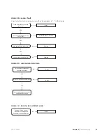
Alarm list
A alarm - Constant alarm
Actions that all alarms cause:
႑
Fan and compressor are blocked.
႑
Relay output ”common alarm” is activated.
႑
Stationary function is activated.
႑
Addition function is activated.
Alarms are reset by restart of the heat pump.
May be due to
Detects by
Alarm type
Incorrectly connected or non-functioning pres-
sure switch. Defective fan or cooling system.
LP sensor (BP2) being cut for at least 2 seconds.
LP alarm
05
Phase failure.
Compressor protection (FC2) has deployed.
Compressor pro-
tection (FC2).
07
Deployed motor circuit breaker.
Incorrect phase sequence.
Phase monitor (BA1) has deployed.
Phase monitor
(BA1).
Compressor protection (FC2) has deployed.
Phase failure.
Poorly bled system.
High pressure switch (BP10) has tripped.
High pressure
switch (BP10).
Clogged particle filter.
The fan blades have jammed.
The fan's internal motor protection has ex-
ceeded 150 ºC (resets automatically when the
temperature has dropped below 115 ºC)
Motor protec-
tion fan
Sensor not connected or defective.
Sensor not con-
nected or defect-
ive.
08
Incorrect sensor value displayed as ”- -” in its
menu as long as measured value is outside the
permitted range.
Faulty wiring between the units or connections.
If communication has been interrupted for five
minutes a Communication alarm is given.
Communication
alarm
09
Heating medium circulates through the condens-
er in wrong direction.
The supply temperature sensor (BT12) is lower
than the return line sensor (BT3) two minutes
after compressor start.
Incorrectly in-
stalled sensor
(supply and re-
turn line sensors
mixed up)
12
The value for the longest permitted defrosting
time in channel A11 may be set too low. Check
sensor.
Defrosting failed three times in a row.
Defrosting
alarm
15
Check the connection difference for the thermo-
stat. Check the start temperature hot water in
any NIBE Indoor module. Check the charge flow
and the particle filter which may be partially
clogged.
The operating time (compressor start until
compressor stop) has been shorter than 120
seconds during all three of the latest compressor
operations.
Short operating
time alarm
16
Poor air flow through the evaporator due to
blockage by snow or leaves. Check sensor.
The hot gas temperature (BT14) exceeds 135
degrees three times within 240 minutes.
Hot gas alarm
17
Program version in control card is older than
v69.
Defrosting starts 10 times in a row with the
safety function.
Low evapora-
tion temperat-
ure
19
15
Chapter 6 |
Troubleshooting
NIBE™ F2300
6 Troubleshooting
Summary of Contents for F2300
Page 1: ...Service manual LEK NIBE F2300 Air water heat pump SEM GB 1335 1 M11450 ...
Page 2: ......
Page 33: ...Electrical circuit diagram 31 Chapter 8 Technical data NIBE F2300 8 Technical data ...
Page 34: ...NIBE F2300 Chapter 8 Technical data 32 ...
Page 35: ...33 Chapter 8 Technical data NIBE F2300 ...
Page 36: ...NIBE F2300 Chapter 8 Technical data 34 ...
Page 42: ......
Page 43: ...NIBE AB Sweden Hannabadsvägen 5 Box 14 SE 285 21 Markaryd info nibe se www nibe eu ...


