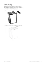
2.
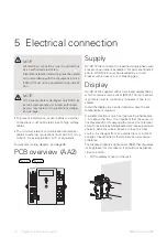
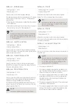
Install the display on the mount by connecting the
connector and then carefully pressing the lower part
of the display against the wall.
Z1
Z2
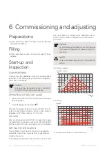
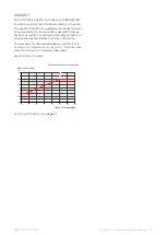
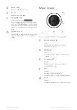
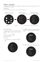
Z3
Z4
C1
C2
C3
C4
UN
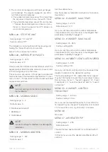
The communication cable to the display is fitted in GV-
HR 120 at the factory and connected to terminal block
21-24 in the display. If the cable needs to be extended,
use a four core cable with a cable area of at least 0.25
mm² for cable lengths up to 50 m. (max. length).
21 22 23 24 C1 C2 C3 C4
1
2
3
4
AA2-L2
AA4
AA2
External connection
options
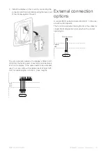
A contact (NO) can be connected to AA2-L1:1-2 to activ-
ate various fan speeds.
The function is activated during the time the contact is
closed. Normal speed is resumed when the contact
opens again.
1
2
AA2-L1
External
AA2
External contact
15
Chapter 5 | Electrical connection
NIBE GV-HR 120-400

