


11
Subject to Technical Modifications of GV-HR110
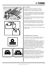
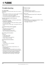
Condensation drain:
When it is time to exchange the filter in the fall, check the
condensation drain for fouling by dirt and make sure there
is water in the waterseal. The waterseal must not dry out
since the negative pressure of the aggregate will suck air
into the aggregate causing the condensation to remain in
the aggregate. Pour 1 litre of water into the condensation
container and check that the flow is undeterred. If the
condensation drain does not work correctly water damages
may occur in the residence.
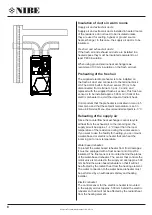
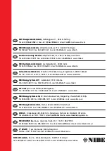
Counter-flow heat exchanger
The counter-flow heat exchanger must be overseen
every year. Remove it if it is dirty and vacuum it without
touching the plates. Open the front of the condensation
container before removing the counter-flow heat
exchanger. This is done by opening the spring latch on
the right corner of the condensation container. Push
lightly from behind when removing the counter-flow heat
exchanger.
Do not damage the plates. The effect will no
longer be optimal if the plates are damaged.
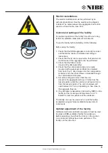
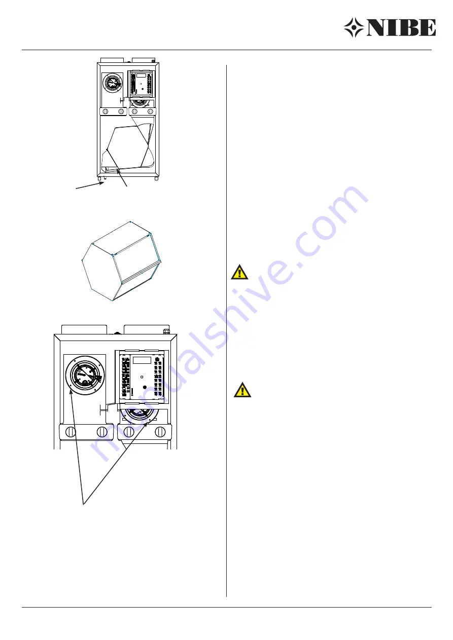
Fans:
Remember to switch of the power supply!!
Check the fans in the fan wheel for dirt every third year.
The four outermost screws that hold the fans in place
must be removed in order to remove the fans. Remove
the front lid of the unit. Clean the fans using a brush, fan
brush or paintbrush.
The filter units must be removed
before disassembling the front lid.
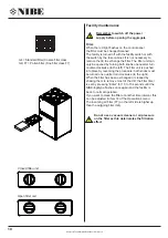
Incoming and outgoing units:
The ventilation unit must be cleaned regularly with a small
brush in order to maintain correct ventilation. Do not
change the setting. N.B. Do not mix the units up when
many are cleaned at the same time.
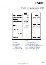
12: Kondensvandsafløb
11: Kondensvandsbakke
9. Udsugningsfilter
7: Udsugningsventilator
6: Indblæsningsventilator
5: Modstrømsvarmeveksler
14: By-pass
13: 230V/50Hz
10: El-kasse
8: Friskluftfilter
4: Indblæsning
3: Udsugning
2: Afkast
1: Frisk luft
3
1
4
2
13
265
128.6
550
280
135
550
24
32
60.7
1014
42
1056
1088
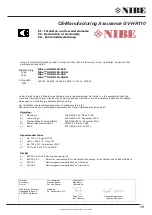
The four outermost screws that hold the fans in
place must be removed in order to remove the
fans.
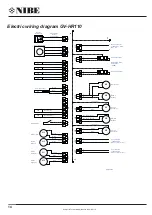
12: Kondensvandsafløb
11: Kondensvandsbakke
9. Udsugningsfilter
7: Udsugningsventilator
6: Indblæsningsventilator
5: Modstrømsvarmeveksler
14: By-pass
13: 230V/50Hz
10: El-kasse
8: Friskluftfilter
4: Indblæsning
3: Udsugning
2: Afkast
1: Frisk luft
3
1
4
2
13
265
128.6
550
280
135
550
24
32
60.7
1014
42
1056
1088
Condensation drain
Counter-flow
heat exchanger
Spring latch,
condensation container


