background image

6

Subject to Technical Modifications of GV-HR110
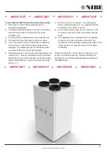
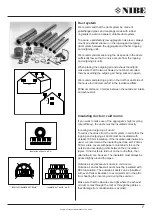
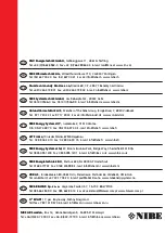
Duct connection

All duct connections have yellow markings that

indicate which ventilation ducts are connected to the

different connections.

Incoming air connection: 

The duct system from the aggregate to the residence.

Outgoing air connection:


The duct system from the residence to the aggregate.

Outside air connection:


The duct system from the outside air hood/outside air grid

or from the ground heat exchanger to the aggregate.

Exhaust air connection: 

The duct systems from the aggregate to the exhaust

air hood/exhaust air grid outdoors.

Optimal operation of the GV-HR110 is achieved by 

mounting a connector piece Ø160 mm in each of the 

four outlets as the first stepp of the duct system. The 

connectors are tightened with the supplied collar bands. 
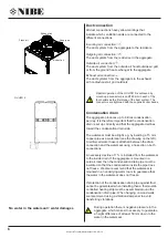
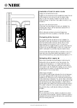
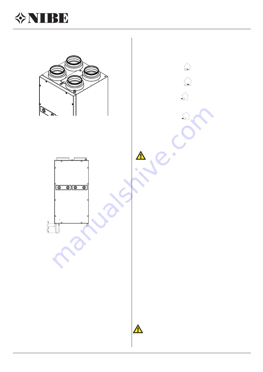
Condensation drain

The aggregate produces up to 6 litres condensation

per day. It is therefore important that the condensation 

drain is set up correctly and that the aggregate declines 

toward the condensation drain side.

The waterseal must be airtight e.g. by bending a 15 mm

copper pipe as a waterseal (see the drawing on the left).

A reinforced water hose is attached between the drain

connection and the waterseal using a hose clip on both

connections.

A necessary decline of 1 % is installed from the waterseal 

to the inside drain. If the aggregate is mounted in a 

cold air room then the condensation drain pipe must be 

insulated so that the condensation inside the pipe does 

not freeze. We also recommend that the waterseal is 

mounted in an underlying warm room to guarantee that 

the water in the waterseal does not freeze.

If protection of the condensation drain pipe against frost 

cannot be guaranteed when installing then a thermostat-

controlled heating strip must be assembled around the 

condensation drain pipe. When hanging on wood walls 

we recommend using a vibration-dampener to avoid 

transferring vibrations.

No water in the waterseal = water damages

During operation there is negative pressure in the

aggregate, which makes it necessary to guarantee 

a height difference of at least 50 mm down to the 

water in the waterseal.
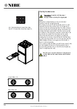
Supply air

Extract air

Fresh air

Exhaust air

GV-HR110

Summary of Contents for GV-HR110

Page 1: ...k NIBE A S Sverigesvej 6 DK 6100 Haderslev Tlf 45 7353 2700 www NIBE dk NIBE AB Sweden Box 14 Hannabadsv gen 5 SE 285 21 Markaryd www NIBE eu INSTALLATIONS MANUAL Passive ventilation Heat recovery GV...

Page 2: ...tics 7 Insulating ducts in warm rooms 8 Reheating of the supply air 8 Electric installations 9 Control and settings of the facility 9 Optimal adjustment of the facility 9 Facility maintenance 10 Troub...

Page 3: ...a thermostat and an electric heating element that switches on when the temperature falls below 2 C IMPORTANT IMPORTANT IMPORTANT IMPORTANT 7 Set the amount of incoming 1 and outgoing air before using...

Page 4: ...r 10 El kasse 11 Kondensvandsbakke 12 Kondensvandsafl b 13 230V 50Hz 14 By pass 2 4 13 72 7 60 7 550 42 1014 24 32 1088 1056 550 135 280 4 Subject to Technical Modifications of GV HR110 GV HR110 Assem...

Page 5: ...in the picture A A Visible wall mountings Concealed wall mountings Cabinet assembly gummif dder som leveret ved vandret montage af maskinen skal de leverede gummif dder flyttes til positioner som anvi...

Page 6: ...he condensation drain side The waterseal must be airtight e g by bending a 15 mm copper pipe as a waterseal see the drawing on the left A reinforced water hose is attached between the drain connection...

Page 7: ...even thicker insulation to avoid warm air in the attic from heating the incoming air during the summer Make sure that the closures are tight where the exhaust air duct comes through the roof or throu...

Page 8: ...ated in menu 4 5 User menu and that the setpoint temperature is set in menu 4 8 Service Menu Recommended setpoint is 3 C Reheating of the supply air Since the counterflow heat exchanger cannot recycle...

Page 9: ...ectly mounted with a waterseal and that it is protected from frost Pour 1 litre of water into the condensation container and check that it flows unimpeded through the condensation drain pipe 5 Set all...

Page 10: ...the procedure both knobs must be turned one quarter turn clockwise to the right When the filter has been exchanged or cleaned by shaking them to remove most of the dirt the filter timer is set by pre...

Page 11: ...amage the plates The effect will no longer be optimal if the plates are damaged Fans Remember to switch of the power supply Check the fans in the fan wheel for dirt every third year The four outermost...

Page 12: ...st No incoming air to the residence Error Faulty fan Fouled incoming air filter Fouled outside air grid A fuse has blown on the circuit board No power supply to the facility No exhaust air from the re...

Page 13: ...Belimo Bypass 230VAC H7 R10 Fan extract air 230VAC H8 R12 ON OFF Bypass 2x230VAC H9 R10 Fan supply air 230VAC bypass H16 R8 AUX relay 230VAC max 20W H17 R9 AUX relay 230VAC max 20W 1 1 1 1 1 1 1 1 1 1...

Page 14: ...Brown Brown Blue Blue Yellow green Yellow green Water valve Belimo Bypass Humidity sensor White Red Blue EC fan Supply air Aux relay R8 1x230V 50Hz ONLY control current Red Brown Blue Green Yellow Wh...

Page 15: ...dards hergestellt Directive a Machinery 2006 42 EC 15 March 2006 b Low Voltage 2006 95 EU 12 December 2006 c Electromagnetic Compatibility 2004 108 EC 15 December 2004 d Radio Telecommunication 99 5 E...

Page 16: ...294 71 Benatky nad Jizerou Tel 420 326 373 801 Fax 420 326 373 803 E mail nibe nibe cz www nibe cz PL NL FI DK DE CZ NIBE Energy Systems OY Juurakkotie 3 01510 Vantaa 3C Broom Business Park Bridge Wa...

Reviews: