background image

MEL  1030, 0040, 1060, 1090, 2090, 2120

22

Installa  on and Opera  on Manual

The electrical module you have bought is designed for hea  ng domes  c hot water and central hea  ng water. It can be in-
stalled in each tank (apart from stainless steel ones) the structure of which (construc  on and size) makes it possible. Before 
installa  on:


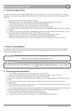
• 

Read this Installa  on and Opera  on Manual carefully.

 • Entrust 

installa  on of the hea  ng module to a quali

fi

 ed person holding appropriate electrical rights.


• 

The electrical wiring system must be made according to binding regula  ons.

 • Before 

star  ng the device, ensure all the connec  ons are correct and   ght.


• 

Provide proper opera  ng condi  ons, according to the device technical speci

fi

 ca  on.


• 

To avoid actua  on of temperature limit fuse, limit the temperature of hea  ng water supplied to the heat exchanger  


down to 80°C.


• 

Check the tank technical speci

fi

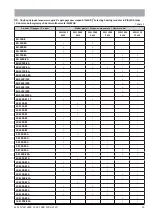
 ca  on. For BIAWAR tanks, select the hea  ng module according to Table 2. The tank  


structure should allow for collision-free installa  on of the hea  ng element inside.


Check the connector pipe diameter – it should correspond with the hea  ng module thread size.


• 

Check the connector pipe length: it must be longer than the hea  ng module dead zone.


• 

Check the material of which the tank is made. The module must not be installed in the stainless-steel tanks.

3. Installa  on requirements

4. Loca  on and installa  on

The electrical module can be installed only horizontally, both in horizontal and in ver  cal tanks whose structure allows for 
installa  on of an electrical module of parameters according to the TECHNICAL DATA table, as well as other requirements 
included in the instruc  ons below.

The module must not be used in the stainless-steel tanks

CAUTION

The hea  ng module must not be installed in the rooms where ambient temperature falls below 5°C or grow up above 

50°C.

CAUTION

5. The hea  ng module installa  on


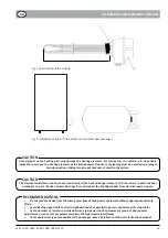
1.  If the module is installed into an already-working device, drain water 

fi

 rst.


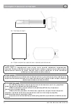
2.  Unscrew the plug protec  ng the connector pipe. Screw-in the electrical module instead of the plug 


(Fig. 1 posi  on 1) – seal the thread with oakum or other sealing  means available.


3.  Screw-in the module so that the supply hose plug is directed down. The module opera  on in a di

 erent posi  on is  

 forbidden.
 

4.  Fill-up the tank, vent the pipe system and then check   ghtness of the hydraulic connec  on at the module 

 installa  on point.
 

5.  If there connec  on is not   ght, drain the tank, seal the connec  on once again and repeat the opera  ons of sec. 2-4.


6.  Unscrew the box front side (Fig. 1 posi  on 2),


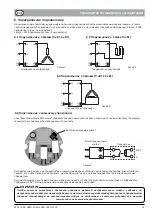
7.  Connect power supply cables to appropriate terminals located in the upper part of the box (posi  on 2) according to  

 the 

connec  on diagram for three-phase or single-phase heaters (see electrical connec  on diagram).


8.  Make the electrical connec  on according to the electrical diagram.


9.  Mount the upper part of the box onto the rest of the hea  ng assembly.

 10. 

Using 

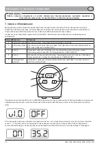
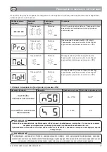
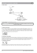
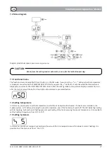
bu  ons, set the required water temperature, see: ACTIVATION AND OPERATION p. 25

GB

Summary of Contents for MEL 0040

Page 1: ...MEL 1030 MEL 0040 MEL 1060 MEL 1090 MEL 2090 MEL 2120 MODU GRZEJNY Z MIKROPROCESOROWYM REGULATOREM TEMPERATURY INSTRUKCJA INSTALACJI I OBS UGI HEATING MODULE WITH MICRO PROCESSOR TEMPERATURE CONTROL...

Page 2: ...elektryczne 6 6 1 Pod czenie do 3 faz 4 kW 6 kW 6 6 2 Pod czenie do 1 fazy 3 kW 6 6 3 Pod czenie do 3 faz 9 kW 12 kW 6 6 4 Pod czenie do sterowania zewn trznego 6 7 Uruchomienie i obs uga 7 7 1 Menu...

Page 3: ...rowie i rodowisko kt ry m g by narasta z powodu niew a ciwego sk adowania odpad w Informacj o punktach utylizacji zu ytego sprz tu elektrycznego i elektronicznego uzyskasz u przedstawiciela lokalnych...

Page 4: ...jscowienie i monta Modu elektryczny mo e by instalowany wy cznie poziomo zar wno w poziomych jak i w pionowych zbiornikach kt rych konstrukcja uwzgl dnia mo liwo instalacji modu u elektrycznego o para...

Page 5: ...z powodu ryzyka zamarzni cia wody w pierwszej kolejno ci nale y od czy modu grzejny od zasilania elektrycznego UWAGA Nie zasila urz dzenia z tych samych linii elektrycznych co urz dzenia wysokiej moc...

Page 6: ...tyku bezpotencja owego Schemat 1 Schemat 2 Przeka nik 230 V N Styk bezpotencja owy Schemat 4 Modu grzejny fabrycznie wyposa ony jest w zwork kt r nale y zast pi przeka nikiem zgodnie ze schematem 3 Je...

Page 7: ...nie aktywne Dla systemu 3 fazowego dioda pulsuje 1o C przed temperatur zadan 3 Przycisk Zmniejsza warto nastawy lub przytrzymuj c ok 3 sekundy zmienia stan sterownika ON OFF wi cej patrz DIAGRAM 4 Prz...

Page 8: ...i szej tabeli zestawiono wszystkie monity alarm w wraz z ich opisem Nazwa funkcji Parametr Zakres nastaw Nastawa producenta NASTAWA TEMPERATURY GRZANIA 15 75 C 50o C NASTAWA HISTEREZY TEMPERATURY 1 10...

Page 9: ...ia temperatur nast puje automatycznie po up ywie 5 sekund liczonych od ostatniego naci ni cia przycisku Poni ej przedstawiony zosta opis parametr w 7 4 Ustawienie temperatury W tym menu u ytkownik ust...

Page 10: ...k Zakres regulacji temperatury 5 75 o C 3 Rozdzielczo pomiar w 0 1 o C Czas pomiar w 0 5 s Odczyt danych Wy wietlacz LED 7 segmentowy Zabezpieczenie Temperaturowe niezale ne STB 95 o C Temperaturowe p...

Page 11: ...MEL 1030 0040 1060 1090 2090 2120 11 1 12 2 12 3 13 4 13 5 13 6 15 6 1 3 4 6 15 6 2 1 3 15 6 3 3 9 12 15 6 4 15 7 16 7 1 ON 17 7 2 18 7 3 18 7 4 18 7 5 18 8 19 9 19 10 19 11 BIAWAR 29 RUS...

Page 12: ...MEL 1030 0040 1060 1090 2090 2120 12 1 Nibe Biawar Sp z o o 2 2006 95 EC 2004 108 EC RUS...

Page 13: ...MEL 1030 0040 1060 1090 2090 2120 13 80oC BIAWAR 2 3 4 5 1 2 1 1 3 4 5 2 4 6 1 2 7 2 8 9 10 16 5oC 50 C RUS...

Page 14: ...MEL 1030 0040 1060 1090 2090 2120 14 L 1 2 RUS...

Page 15: ...030 0040 1060 1090 2090 2120 15 6 3 400 3 1 230 1 6 1 3 4 6 L1 L1 N N L2 L3 L2 L3 H1 H2 H3 L1 L1 N N L2 L3 L2 L3 H1 H2 H3 6 2 1 3 6 4 MEL 1 2 230 V N 4 3 EOn L1 L1 N N L2 L3 L2 L3 H1 H2 H3 6 3 3 9 12...

Page 16: ...MEL 1030 0040 1060 1090 2090 2120 16 7 230 1 400 3 1 2 3 1oC 3 3 ON OFF 4 3 5 ON OFF C o 25 6 1 2 3 4 5 MEL 230 400 OFF 3 ON RUS...

Page 17: ...MEL 1030 0040 1060 1090 2090 2120 17 85 oC Protect OFF No Liquid OFF No Hea ng OFF 15 75 C 50o C 1 10 C 2o C 7 1 ON RUS...

Page 18: ...MEL 1030 0040 1060 1090 2090 2120 18 7 2 7 3 ON 3 5 7 4 3 3 0 5 C 15 75 C 7 5 1 10 C 5 RUS...

Page 19: ...MEL 2090 MEL 2120 3 kW 4 kW 6 kW 9 kW 12 kW NTC 10 k 5 75 o C 3 0 1 o C 0 5 s 7 STB 95 o C 80 o C 1 C 3 60 NTC 10 230 V 400 V 13 1 A 5 8 A 8 7 A 13 1 A 17 4 A 5 C 50 C 1 3 1 4 1 5 1 7 1 8 1 9 IP 54 1...

Page 20: ...n 22 6 Electrical connec on 24 6 1 Connec ng to 3 phases 4 kW 6 kW 24 6 2 Connec ng to 1 phase 3 kW 24 6 3 Connec ng to 3 phases 9 kW 12 kW 24 6 4 Connec ng to external control 24 7 Ac va on and Opera...

Page 21: ...resources and prevents nega ve impact to human health and the environment which could increase due to incorrect waste disposal Informa on on waste equipment management points is available from local...

Page 22: ...le can be installed only horizontally both in horizontal and in ver cal tanks whose structure allows for installa on of an electrical module of parameters according to the TECHNICAL DATA table as well...

Page 23: ...the risk of water freezing first disconnect the hea ng module from electrical power supply CAUTION Do not feed the device from the same power lines as high power equipment without appropriate network...

Page 24: ...ontact Diagram 1 Diagram 2 Relay 230 V N Poten al free contact Diagram 4 The hea ng module is factory equipped with a jumper pin which must be replaced with a relay according to Diagram 3 If the relay...

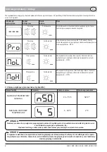
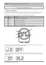
Page 25: ...s if hea ng is ac vated For the 3 phase system the LED starts pulsing 1oC before the pre set temperature 3 Bu on Reduces the pre set value or if pressed for approx 3 seconds changes the controller sta...

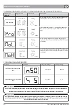
Page 26: ...The following table includes all alarm messages with descrip ons Func on Parameter Range of se ngs Factory se ng HEATING TEMPERATURE SET 15 75 C 50o C TEMPERATURE HYSTERESIS SET 1 10 C 2o C 7 1 Func o...

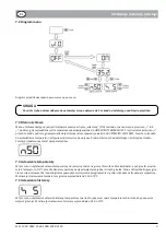
Page 27: ...temperature display is automa c 5 sec a er the last pressing of the bu on Descrip on of parameters is presented below 7 4 Se ng temperature In this menu you are able to set the temperature to which t...

Page 28: ...rement resolu on 0 1 o C Time of measurements 0 5 s Reading data 7 segment LED display Protec on Temperature independent STB 95 o C Temperature programmable 80 o C Detec ng lack of water detec ng incr...

Page 29: ...8A BU 300 8A BU 500 8A BU 750 8A BU 1000 8A BUW 300 8A BUW 500 8A BUW 750 8A BUW 1000 8A BUZ 400 150 BUZ 500 200 BUZ 500 300 BUZ 750 200 BUZ 1000 200 W E 400 81 PC W E 100 81 W E 125 81 W E 150 81 W...

Page 30: ...ku zasilania energii elektrycznej uszkodze powsta ych na skutek przepi burz powodzi po ar w i podobnych zdarze losowych uszkodze powsta ych wskutek niew a ciwej instalacji i monta u element w eksploat...

Page 31: ...WY W d KZ WK W Zt Ed 1 KUPON 3 KUPON 2 KUPON W d WK W Zt Ed hWKE d B E D K Z hE h W d WK W Zt Ed hWKE d B E D K Z hE h W d WK W Zt Ed hWKE d B E D K Z hE h DATA NAPRAWY NR RACHUNKU DATA NAPRAWY NR RAC...

Page 32: ...W WZ t z d WZ z zd Ez WK W Ed d WZ z W d WK W WZ t z KdZK K_ W d WK W WZ t z d WZ z zd Ez WK W Ed DATA PRODUKCJI DATA PRODUKCJI W d WK W WZ t z d WZ z zd Ez WK W Ed DATA PRODUKCJI KUPON INSTALACJI ZER...

Reviews: