26
POOL 11
GB
LE
K
LE
K
LE
K
LE
K
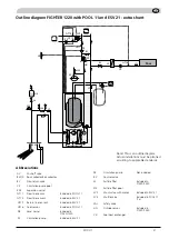
Pressure/level monitor brine
GT15 External compensation 2
GT16 Pool temperature
X1
-E2
EVB-Card
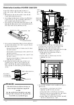
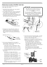
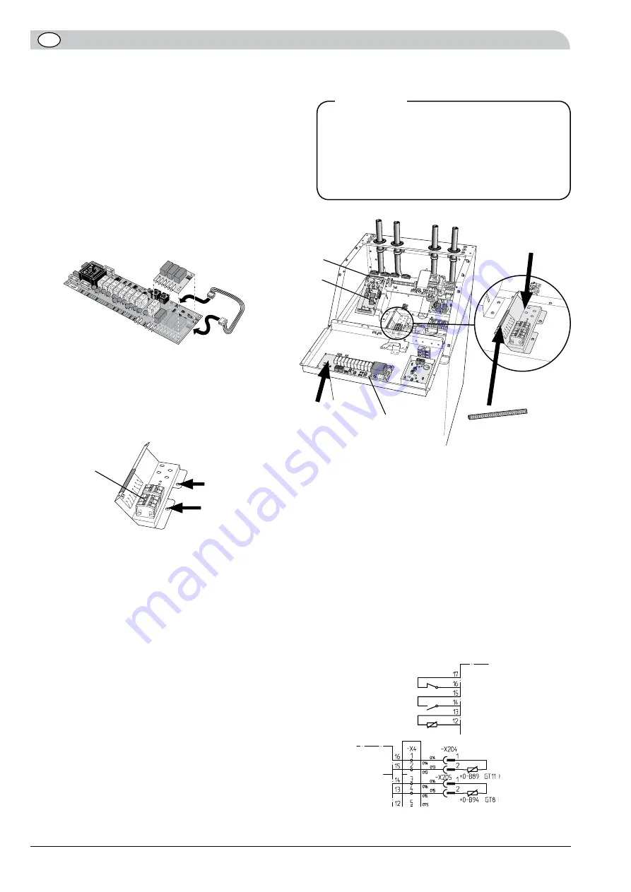
1. Install the edge protection on the sharp edge, see the
right image.
2. The supplied relay card (-E34) is installed on the exist-
ing relay card (-E29) using plastic turrets, see image
below.
3. Connect the edge connector wiring between the
supplied relay card (–E34) and relay card (–E29) as
illustrated below.
All electrical connections must be carried
out by an authorised electrician.
Electrical installation and wiring must be
carried out in accordance with the stipula-
tions in force.
Note!
Electrical connection
M4, self-tapping
torx screws
–X6
HAHN
LEK
Relay card, –E34
Relay card, –E29
Edge board wiring
Electrical
connection
–X6
Edge protection
–E29
Room for
–E34
–E2
–X1
4. Install connection terminals, labels and strain relief
on the panel. Screw the plate into place with two
accompanying M4 self-tapping screws, see image
below.
X4
Return
sensor 1
Flow
sensor 1
5. The corresponding brown wiring with flat pin sleeves
and zero numbers 0121, and 0123 are installed as
follows:
- Loose end of 0121 to spring terminal –X6:2.
- Flat pin sleeve with cable 0121/0122 to –E34:37.
- Flat pin sleeve with cable 0122/0123 to –E34:39.
- Single flat pin sleeve with cable 0123 to –E34:41.
6. Connect the other single cables as follows:
- Blue cable with zero number 0118 between
screw terminal –X6:18 to spring terminal –X6:3.
- Brown cable with zero number 0119 between
screw terminal –X6:19 to spring terminal –X6:1.
- Brown cable with zero number 0120 between
screw terminal –X6:16 to spring terminal –X6:2.
- Yellow/green cable with zero number 0108 to
spare earth connection (-PE) and in spring terminal
–X6:4
- Brown cable with zero number 0105 to flat pin –
E34:38 and in spring terminal –X6:5.
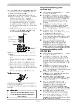
7. The sensors are connected by twin cables (for exam-
ple EKXX or LiYY) as follows for the load monitor
card, EBV– E2 see image below:
Use the following round pin sleeves for splicing be-
tween the 2-cables and sensors GT11 & GT16.
- Connect the sensor used as the flow sensor (GT
11) to terminal –E2:X4:15 and – E2: X4:16 in
the load monitor card’s lower terminal block.
Disconnect the existing sensor from –X204:1 and
– X204:2 (positioned above the cooling module).
- Connect pool sensor (GT 16) to terminal –
E2: X1:12 and –E2:X1:13 on the load monitor
card’s upper terminal block.
Electrical connection FIGHTER 1120/1140
Following cable for Pool 11 used in this kit:
0105, 0108, 0118 to 0123.
Summary of Contents for POOL 11
Page 2: ......
Page 16: ...14 POOL 11...
Page 30: ...28 POOL 11...
Page 44: ...42 POOL 11...
Page 45: ...43 POOL 11 Elschema SE DE GB Wiring Diagram Elektrischer Schaltplan...
Page 47: ...45 POOL 11 Elschema Wiring Diagram Elektrischer Schaltplan FIGHTER 1235 1240 1250...
Page 48: ...46 POOL 11 Elschema Wiring Diagram Elektrischer Schaltplan FIGHTER 1235 1240 1250...
Page 49: ...47 POOL 11 Elschema Wiring Diagram Elektrischer Schaltplan FIGHTER 1220 1230...
Page 50: ...48 POOL 11 Elschema Wiring Diagram Elektrischer Schaltplan FIGHTER 1120 1130 1135 1140...
Page 51: ......


