7
Buff er tanks
UKV 20-220/300/500/750/1000
3. INSTALLATION
3.1 Locati on of the Tank
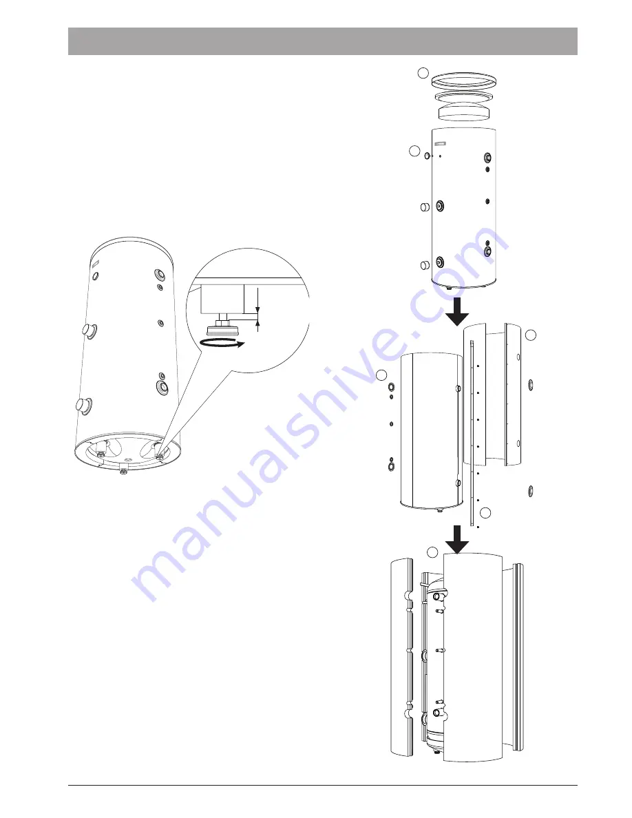
0-15 mm
Fig. 10
Levelling the unit.
3.2 Housing Disassembly
Removable housing with thermal insulati on facilitate trans-
port and installati on of the tank. Disassembly the housing in
the following order (see Fig. 11):
Aft er the installati on of the tank in its fi nal locati on, reinstall
the removed components in the reverse order.
Fig. 11
Housing disassembly
1. Remove the Temperature gauge and plugs of the heati ng
element connector pipes.
2. Remove the upper cover of the housing together with
thermal insulati on.
3. Remove the plugs from the connector pipes and black
bushings.
4. Remove the fi xing screws and the strip connecti ng the
housing jacket.
5. Remove the jacket surrounding the tank (housing jacket.)
6. Remove the four-piece thermal insulati on.
1
2
3
4
5
6
Buff er tanks of UKV Series should be installed in a dry area,
protected against temperatures below 0°C (e.g. in the base-
ment, boiler room, etc.). Locati on and manner of installati on
must ensure trouble-free maintenance and servicing of the
unit in the future.
Select the device locati on in a way allowing the rati onal ro-
uti ng of the central heati ng system. We recommend installa-
ti on of the buff er tanks in the immediate vicinity of the main
heat source in order to avoid unnecessary heat losses. Consi-
der the fi lled tank weight when selecti ng its locati on as well as
free space above and on the sides of the buff er tank required
to perform maintenance and inspecti ons of the unit.
The tank stands on three adjustable feet that can be adjusted
within the range from 0 to 15 mm to level the tank.
INSTALLATION AND OPERATING MANUAL
Summary of Contents for UKV 20-1000
Page 14: ...14 Buffer tanks UKV 20 220 300 500 750 1000 NOTES NOTES ...
Page 15: ......


