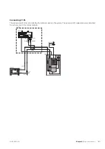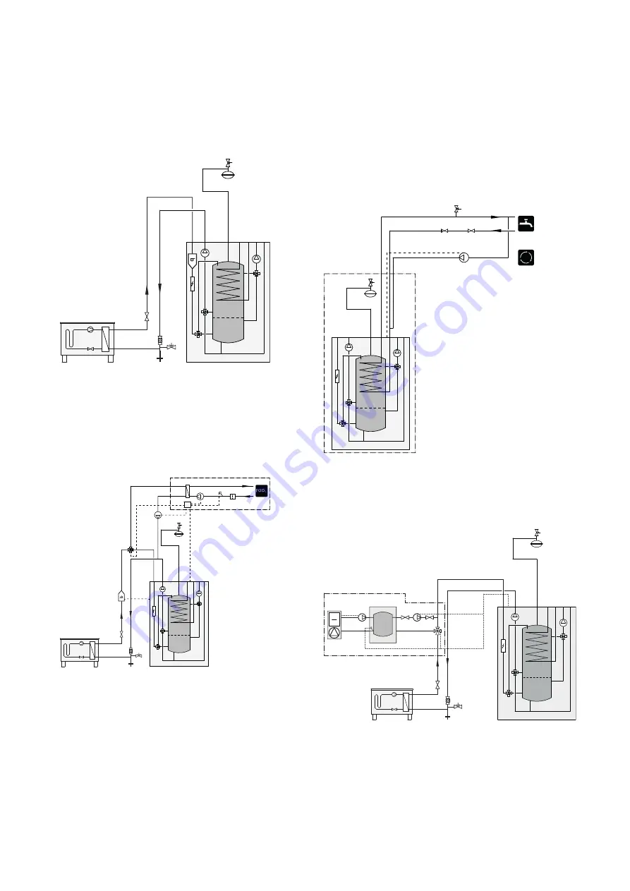
Connecting EMK 310
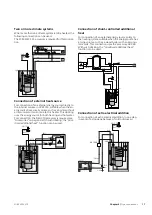
Installing energy measurement kit EMK 310* (BF1) to
VVM 310.
-EB15-FL2
-EB15
-CM1
-EB15
-XL8
-XL9
-EB101
-XL2
-XL1
-QM1
-FL10
-QM40
-QZ2
-EB15
-BF1
*Energy meter (BF1) included in VVM 310 EMK. Available as access-
ory EMK 310 for other markets.
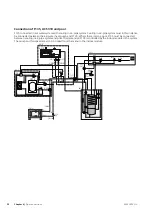
Connecting EMK 300
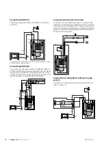
Connecting energy measurement kit EMK 300 (BF2) to
VVM 310. EMK 300 is connected between the air/water
heat pump and VVM 310, although before the first ac-
cessory. This accessory is used if energy measurement of
pool or cooling in a 4-pipe system is required.
-EB15
-FL2
-EB15
-CM1
-EB15
-XL8
-XL9
-EB101
-XL2
-XL1
-QM1
-FL10
-QM40
-QZ2
-EB15
-BF2
-GP9 -BT51 -HQ4
-EP5
-AA25
-CL11
-CL11-QN19
-CL11
-GP12
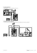
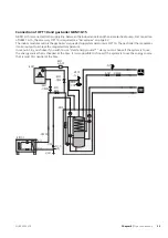
Connecting hot water circulation
To reduce the risk of bacterial growth in systems with
hot water circulation, the temperature of the circulating
water should not fall below 50 °C. There should not be
any non-circulatory hot water pipes. Adjust the hot water
system so that the temperature does not fall below 50 °C
at the ends of the system.
-FL2
-CM1
-EB15
-EB15
-FL1
-QM40
-RM1
-GP11
XL3
XL4
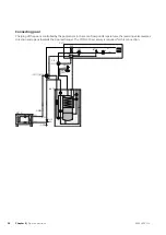
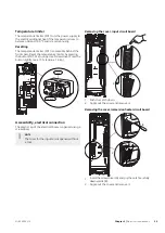
Connection of integrated cooling in 4-pipe
system
Connection of integrated cooling in 4-pipe system via
AUX in VVM 310.
-EB101
-XL2
-XL1
-QM1
-FL10
-QM40
-QZ2
-EB15-FL2
-EB15
-CM1
-EB15
-EQ1
-GP13
-CP10
-BT64
-QM42
-QM41
-GP12
-QN12
NIBE VVM 310
Chapter 4 |
Pipe connections
18
Summary of Contents for VVM 310 EMK
Page 1: ...Installer manual APH NIBE VVM 310 EMK Indoor module IHB EN 1750 8 231175 ...
Page 69: ...Electrical wiring diagram 3x400 V 69 Chapter 12 Technical data NIBE VVM 310 ...
Page 70: ...NIBE VVM 310 Chapter 12 Technical data 70 ...
Page 71: ...71 Chapter 12 Technical data NIBE VVM 310 ...
Page 72: ...NIBE VVM 310 Chapter 12 Technical data 72 ...
Page 73: ...73 Chapter 12 Technical data NIBE VVM 310 ...
Page 76: ......
Page 77: ......
Page 78: ......


