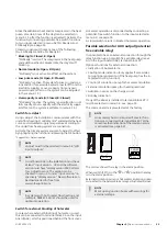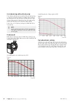
Possible selection for AUX inputs
Supply line, cooling (BT64)
The temperature sensor for cooling is used when internal
“active cooling 4-pipe” has been activated in the output
AA3-X7. The sensor is used for calculating degree
minutes for cooling.
Temperature sensor, cooling/heating/hot water
An extra temperature sensor can be connected to VVM
310 in order to determine when it is time to switch
between cooling, heating and hot water operation.
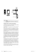
Connect the temperature sensor to selected input (menu
5.4, the option only shows if the cooling accessory is in-
stalled, see page 55) on terminal block X6 on the input
board (AA3) which is located behind the front cover and
is to be placed in a suitable location in the climate system.
Use a 2 core cable of at least 0.5 mm2 cable area.
Switch for external blocking of additional heat or
compressor
When external blocking of additional heat and/or com-
pressor is wanted, this can be connected to terminal
block X6 on the input board (AA3), which is positioned
behind the front cover.
The additional heat and/or the compressor are discon-
nected by connecting a potential-free switch function
to the input selected in menu 5.4, see page 55.
External blocking of addition and compressor can be
combined.
A closed contact results in the electrical output being
disconnected.
Contact for external tariff blocking
In those cases where external tariff blocking is used, it
can be connected to terminal block X6 on the input
board (AA3), which is positioned behind the front cover.
Tariff blocking means that the additional heat, the
compressor, the heating and hot water are blocked by
connecting a potential-free switch function to the input
selected in menu 5.4, see page 55.
Closed switch means that tariff blocking is activated.
NOTE
When tariff blocking is activated, the min.
supply line does not apply.
Switch for external blocking of heating/cooling
In cases where external blocking of heat/cooling is used,
it can be connected to terminal block X6 on the input
board (AA3), which is positioned behind the front cover.
Heating/cooling operation is disconnected by connecting
a potential-free switch function to the input selected in
menu 5.4, see page 55.
A closed switch results in blocked heating/cooling oper-
ation.
NOTE
When heat blocking is activated, the min. sup-
ply line does not apply.
Switch for external alarm (NC)
If ”switch for external alarm (NC)” is selected as function
on a soft input, infolarm 995 appears if the connected
external circuit for selected soft input is
open
.
Switch for external alarm (NO)
If "switch for external alarm (NO)" is selected as function
on a soft input, infolarm 995 appears if the connected
external circuit for selected soft input is
closed
.
Contact for activation of “activate temp lux"
An external switch function can be connected to VVM
310 for activation of the hot water function "activate
temp lux". The switch must be potential-free and connec-
ted to the selected input (menu 5.4, see page 55) on
terminal block X6 on the input board (AA3).
"activate temp lux" is activated for the time that the
contact is connected.
Contact for activation of “external adjustment"
An external contact function can be connected to VVM
310 to change the supply temperature and the room
temperature.
When the switch is closed the temperature changes in
°C (if the room sensor is connected and activated). If a
room sensor is not connected or activated, the desired
change of "temperature" (heating curve offset) with the
number of steps selected is set. The value is adjustable
between -10 and +10.
■
climate system 1
The switch must be potential-free and connected to
the selected input (menu 5.4, see page 55) on terminal
block X6 on the input board (AA3).
The value for the change is set in menu 1.9.2, "external
adjustment".
■
climate system 2 to 8
External adjustment for climate systems 2 to 8 requires
accessories (ECS 40 or ECS 41).
See the accessory’s installer handbook for installation
instructions.
Switch for "SG ready"
NOTE
This function can only be used in mains net-
works that support the "SG Ready"-standard
(Germany).
"SG Ready" requires two AUX inputs.
In cases where this function is required it must be con-
nected to terminal block 6 on the input board (3).
"SG Ready" is a smart form of tariff control, through
which your electricity supplier can affect the indoor, hot
water and/or pool temperatures (if applicable) or simply
NIBE VVM 310
Chapter 5 |
Electrical connections
32
Summary of Contents for VVM 310 EMK
Page 1: ...Installer manual APH NIBE VVM 310 EMK Indoor module IHB EN 1750 8 231175 ...
Page 69: ...Electrical wiring diagram 3x400 V 69 Chapter 12 Technical data NIBE VVM 310 ...
Page 70: ...NIBE VVM 310 Chapter 12 Technical data 70 ...
Page 71: ...71 Chapter 12 Technical data NIBE VVM 310 ...
Page 72: ...NIBE VVM 310 Chapter 12 Technical data 72 ...
Page 73: ...73 Chapter 12 Technical data NIBE VVM 310 ...
Page 76: ......
Page 77: ......
Page 78: ......

