Preparations
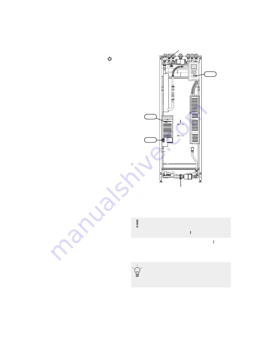
1. Check that the switch (SF1) is in position " ".
2. Check that the drain valve is fully closed and that the
temperature limiter (FD1) has not deployed.
3. Compatible NIBE air/water heat pump must be
equipped with a control board with display that has
at least the software version as listed on page 14.
The control board version is displayed in the heat
pump’s display at start-up.
Filling and venting
Filling the hot water coil
1. Open a hot water tap in the house.
2. Open the externally mounted shut-off valve. This
valve should then be fully open during operations.
3. When water comes out of the hot water tap, the hot
water coil is full and the tap can be closed.
Filling the climate system
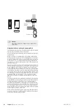
1. Open the vent valve (QM20).
2. Open the externally mounted filler valve. The boiler
section and the rest of the climate system are filled
with water.
3. When the water exiting the vent valve (QM20) is not
mixed with air, close the vent valves. After a while
the pressure rises on the externally mounted pres-
sure gauge. When the opening pressure for the ex-
ternally mounted safety valve has been reached, it
starts to release water. Close the filler valve.
4. Open the externally mounted safety valve until the
pressure in VVM 310 falls to the normal working
range (approx. 1 bar) and check that there is no air
in the system by turning the vent valves (QM20).
Venting the climate system
1. Cut the power to VVM 310.
2. Vent VVM 310 through the vent valve (QM20) and
other climate systems through their relevant vent
valves.
3. Keep topping up and venting until all air has been
removed and the pressure is correct.
W
ilo
W
ilo
VVM 310
Venting valve (QM20)
Drain valve (QM1)
FD1
FA1
SF1
Start-up and inspection
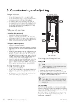
Start guide
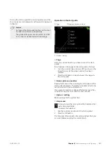
NOTE
There must be water in the climate system be-
fore the switch is set to " ".
1. Set switch (SF1) on VVM 310 to position " ".
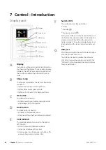
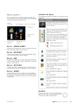
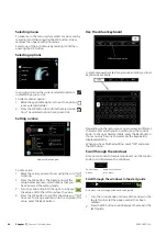
2. Follow the instructions in the display's start guide.
If the start guide does not start when you start the
VVM 310, start it manually in menu 5.7.
TIP
See page 42 for a more in-depth introduction
to the installation’s control system (operation,
menus etc.).
Commissioning
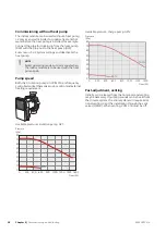
The first time the installation is started a start guide is
started. The start guide instructions state what needs to
carried out at the first start together with a run through
of the installation’s basic settings.
The start guide ensures that start-up is carried out cor-
rectly and cannot be bypassed.The start guide can be
started later in menu 5.7.
NIBE VVM 310
Chapter 6 |
Commissioning and adjusting
36
6 Commissioning and adjusting
Summary of Contents for VVM 310 EMK
Page 1: ...Installer manual APH NIBE VVM 310 EMK Indoor module IHB EN 1750 8 231175 ...
Page 69: ...Electrical wiring diagram 3x400 V 69 Chapter 12 Technical data NIBE VVM 310 ...
Page 70: ...NIBE VVM 310 Chapter 12 Technical data 70 ...
Page 71: ...71 Chapter 12 Technical data NIBE VVM 310 ...
Page 72: ...NIBE VVM 310 Chapter 12 Technical data 72 ...
Page 73: ...73 Chapter 12 Technical data NIBE VVM 310 ...
Page 76: ......
Page 77: ......
Page 78: ......

