background image

Menu 5.3.19 - active cooling 4 pipe

Here you select which pump to use in the system.

Menu 5.3.20 - flow sensor

EMK 500

flow sensor

flow sensor 5.3.20

flow sensor

Setting option: EMK 500, EMK 300 / 310, EMK 150

Factory setting: EMK 500

Here you select which flow sensor is used for the energy
measurement.

Menu 5.3.21 - external energy meter

set mode

Setting range: energy per pulse / pulses per kWh

Default value: energy per pulse

energy per pulse

Setting range: 0 – 10000 Wh

Factory setting: 1000 Wh

pulses per kWh

Setting range: 0 – 10000

Factory setting: 500

The energy meter(s) are used to send pulse signals every
time a certain amount of energy has been consumed.

energy per pulse:

Here you set the amount of energy

each pulse is to correspond to.

pulses per kWh:

Here you set the number of pulses per

kWh that are sent to VVM 310.

Menu 5.4 - soft in/outputs

Here you can select the in/output on the input circuit
board (AA3) the external contact function (page 31) is
to be connected to.

Selectable inputs on terminal block AUX1-5 (AA3-X6:9-
18) and output AA3-X7 (on the input circuit board).

Menu 5.5 - factory setting service

All settings can be reset (including settings available to
the user) to default values here.

NOTE

When resetting, the start guide is displayed the
next time the indoor module is restarted.

Menu 5.6 - forced control

You can force control the different components in the
indoor module and any connected accessories here.

NOTE

Forced control is only intended to be used for
troubleshooting purposes. Using the function
in any other way may cause damage to the
components in your climate system.

Menu 5.7 - start guide

When the indoor module is started for the first time the
start guide starts automatically. Start it manually here.

See page 36 for more information about the start guide.

Menu 5.8 - quick start

It is possible to start the compressor from here.

Caution

There must be a heating or hot water demand
to start the compressor.

Caution

Do not quick start the compressor too many
times over a short period of time as this may
damage the compressor and its surrounding
equipment.

Menu 5.9 - floor drying function

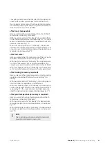
length of period 1 – 7

Setting range: 0 – 30 days

Factory setting, period 1 – 3, 5 – 7: 2 days

Factory setting, period 4: 3 days

temp. period 1 – 7

Setting range: 15 – 70 °C

Default value:

20 °C

temp. period 1

30 °C

temp. period 2

40 °C

temp. period 3

45 C

temp. period 4

40 °C

temp. period 5

30 °C

temp. period 6

20 °C

temp. period 7

55

Chapter 8 |

Control - Menus

NIBE VVM 310

Summary of Contents for VVM 310 EMK

Page 1: ...Installer manual APH NIBE VVM 310 EMK Indoor module IHB EN 1750 8 231175 ...

Page 2: ... described on page 43 Set the indoor climate 2X MY INSTALLATION INDOOR CLIMATE HOT WATER INFO The mode for setting the indoor temperature is accessed by pressing the OK button twice when in the start mode in the main menu Increase hot water volume 2X 1X INDOOR CLIMATE HOT WATER MY INSTALLATION INFO To temporarily increase the amount of hot water first turn the control knob to mark menu 2 water dro...

Page 3: ...adjusting 36 Preparations 36 Filling and venting 36 Start up and inspection 39 Setting the cooling heating curve 40 Setting hot water circulation 40 Pool 40 SG Ready 42 7 Control Introduction 42 Display unit 43 Menu system 46 8 Control Menus 46 Menu 1 INDOOR CLIMATE 47 Menu 2 HOT WATER 47 Menu 3 INFO 48 Menu 4 MY SYSTEM 49 Menu 5 SERVICE 58 9 Service 58 Service actions 61 10 Disturbances in comfor...

Page 4: ... may drip from the safety valve s overflow pipe so this pipe must be inclined along its entire length to prevent water pockets It must also be frost proof The over flow pipe must be visible and its outlet must be open NOTE VVM 310 must be installed with a disconnection option on the supply cable Minimum cable area must be sized according to the fuse rating used All installations must be car ried o...

Page 5: ...ecovery Leave the disposal of the packaging to the in staller who installed the product or to special waste stations Do not dispose of used products with normal household waste It must be disposed of at a special waste station or dealer who provides this type of service Improper disposal of the product by the user results in administrative penalties in accordance with current legis lation 5 Chapte...

Page 6: ...ting medium page 16 System flushed System vented Expansion vessel Particle filter Safety valve Shut off valves Boiler pressure Connected according to outline diagram Hot water page 16 Shut off valves Mixing valve Safety valve Electricity page 24 Connected communication Circuit fuses Fuses indoor module Fuses property Outside sensor Room sensor Current sensor Safety breaker Earth circuit breaker Se...

Page 7: ...or hot water when connected to VVM 310 the space where VVM 310 is located must be provided with a floor drain Not enclosed Installation area Leave a free space of 800 mm in front of the product All service on VVM 310 can be carried out from the front 800 NOTE Leave 10 25 mm free space between the in door module and the wall behind for routing of cables and pipes Supplied components Room sensor Out...

Page 8: ... The side covers can be removed to facilitate the installa tion Caution 50 mm space required to remove the side panels 1 Remove the screws from the upper and lower edges 2 Twist the cover slightly outward 3 Move the hatch backwards and slightly to the side 4 Pull the cover to one side 5 Pull the hatch forwards LEK LEK LEK NIBE VVM 310 Chapter 2 Delivery and handling 8 ...

Page 9: ...BT63 UB2 BF1 BT6 BT54 XL30 AA7 XL18 XL3 XL4 XL8 XL19 QN11 AA1 X3 BT30 AA1 X1 AA1 X7 AA1 S2 AA1 AA3 X4 BP5 QN35 UB1 UB2 K1 PF3 XL1 XL2 BT3 BT2 AA4 W130 SF1 QN10 BT7 XL9 PF1 PF4 Applies to VVM 310 EMK Available as accessory EMK 310 for other markets 9 Chapter 3 Indoor module s design NIBE VVM 310 3 Indoor module s design ...

Page 10: ...ure sensor hot water charging BT6 Temperature sensor hot water top BT7 Thermostat standby mode BT30 Temperature sensor external docking BT54 Temperature sensor heating medium supply after immersion heater BT63 Electrical components Immersion heater card AA1 AA1 S2 Switch DIP switch on circuit board AA1 X1 Terminal block incoming AA1 X3 Terminal block immersion heater AA1 X7 Terminal block immersio...

Page 11: ...n extra water filter NOTE Any high points in the climate system must be equipped with air vents NOTE The pipe systems need to be flushed out before the indoor module is connected so that any debris cannot damage component parts NOTE Switch SF1 must not be moved to or until VVM 310 has been filled with water Otherwise the temperature limiter thermostat and the immersion heater etc can be damaged Bo...

Page 12: ...10 and if the outdoor air temperature falls below the heat pump stop temperature all heating is carried out by VVM 310 EB15 FL2 EB15 CM1 EB15 FL1 QM40 RM1 EB101 XL2 XL1 QM1 FL10 QM40 QZ2 Symbol key Meaning Symbol Venting valve Shut off valve Tapping valve Non return valve Filterball Trim valve Shunt shuttle valve Safety valve Filterball Thermometer T Temperature sensor Expansion vessel Pressure ga...

Page 13: ...nection heating medium return line G20 int XL2 Connection cold water G20 int XL3 Connection hot water G20 int XL4 Connection docking in heating medium G20 int XL8 Connection docking out heating medium G20 int XL9 Connection solar heating system supply line Ø22 mm XL13 Connection solar heating system return line Ø22 mm XL14 Connection docking in high temp Ø22 mm XL18 Connection docking out high tem...

Page 14: ... versions F2120 all versions NIBE SPLIT HBS 05 AMS 10 6 HBS 05 6 AMS 10 8 HBS 05 12 AMS 10 12 HBS 05 12 AMS 10 16 HBS 05 16 VVM 310 can be connected to extra water heater see below Further option information is available at nibe eu and in the respective assembly instructions for the accessories used See page 63 for the list of the accessories that can be used with VVM 310 Extra hot water heaters W...

Page 15: ...ank CP2 Charge pump external heat source GP15 Non return valve RM1 Climate system 2 EP21 Unit box with accessory card AA25 Temperature sensor heating medium flow BT2 Temperature sensor heating medium return BT3 Circulation pump heating medium lower shunt GP20 Shunt valve QN25 Solar kit EP30 Unit box with accessory card AA25 Temperature sensor solar panel BT53 Expansion vessel CM5 Solar panel EP8 P...

Page 16: ... to the heat pump XL9 EB15 FL2 EB15 CM1 EB15 XL8 XL9 Connecting cold and hot water A mixer valve must be installed if the factory setting is changed so that the temperature can exceed 60 C Na tional regulations must be observed The setting is made in menu 5 1 1 See page 50 EB15 FL2 XL4 XL3 EB15 CM1 EB15 FL1 QM40 RM1 Connecting the climate system When connecting to a system with thermostats on all ...

Page 17: ...ssories on page 63 With such docking the prior itised additional heat function can be used EB15 FL2 EB15 CM1 EB15 XL18 XL19 BT52 EM1 AA25 EM1 GP15 RM1 Connection of shunt controlled additional heat For connection of an external energy source solely to the heating system suitable when the energy source has a large volume such as a wood boiler with an accumu lator tank This connection uses the acces...

Page 18: ...5 XL8 XL9 EB101 XL2 XL1 QM1 FL10 QM40 QZ2 EB15 BF2 GP9 BT51 HQ4 EP5 AA25 CL11 CL11 QN19 CL11 GP12 Connecting hot water circulation To reduce the risk of bacterial growth in systems with hot water circulation the temperature of the circulating water should not fall below 50 C There should not be any non circulatory hot water pipes Adjust the hot water system so that the temperature does not fall be...

Page 19: ... BT64 QN12 AA25 EQ1 GP13 GP12 QM41 QM42 Connecting to solar installation For connection to solar installation the SCA 35 accessory is required see Accessories on page 63 T P T FL2 CM1 XL13 XL14 EB15 EB15 EB15 EP30 BT53 EP8 AA5 GP30 RM4 GP4 EP5 RM3 GP4 CM5 FL4 OM44 OM43 OM45 EB101 XL2 XL1 QM1 FL10 QM40 QZ2 19 Chapter 4 Pipe connections NIBE VVM 310 ...

Page 20: ...ool temperatures the reversing valve reverses direction and opens towards the pool exchanger The POOL 310 accessory is required for this connection EB15 FL2 EB15 CM1 EB15 EB101 XL2 XL1 QM1 FL10 QM40 QZ2 GP9 BT51 HQ4 EP5 AA25 CL11 CL11 QN19 CL11 GP12 NIBE VVM 310 Chapter 4 Pipe connections 20 ...

Page 21: ...d by the indoor module in the system The pump and fan speed are also controlled from the menu in the indoor module EB15 FL2 EB15 CM1 EB15 RM1 EB101 XL2 XL1 QM1 FL10 QM40 QZ2 AZ10 AZ10 HQ1 GP10 QM42 QM43 RM1 21 Chapter 4 Pipe connections NIBE VVM 310 ...

Page 22: ...ol F135 must be connected between cooling in a 4 pipe system and pool The demand on F135 is controlled by the indoor module in the system The pump and fan speed are also controlled from the menu in the indoor module EB15 FL2 EB15 CM1 EB15 EB101 XL2 XL1 QM1 FL10 QM40 QZ2 GP9 BT51 HQ4 EP5 AA25 CL11 CL11 QN19 CL11 GP12 CP10 BT64 QN12 AA25 EQ1 GP13 GP12 AZ10 AZ10 RM1 QM44 HQ1 GP10 QM42 QM43 NIBE VVM 3...

Page 23: ...ia OPT 10 The gas boiler then regulates its own output to achieve the requested temperature In menu 4 1 8 you choose if you wish to use smart energy source Here you can choose if the system is to use the energy source that is cheapest at the time It is also possible to choose if the system is to use the energy source that is most CO2 neutral at the time EB15 FL2 EB15 CM1 EB15 FL1 QM40 RM1 EB101 XL...

Page 24: ...il the boiler has been filled with water and the radiator system vented Otherwise the temperaturelimiter thermostatandtheimmer sion heater can be damaged NOTE If the supply cable is damaged only NIBE its service representative or similar authorised person may replace it to prevent any danger and damage NOTE Electrical installation and service must be car ried out under the supervision of a qualifi...

Page 25: ...y max 15 N approx 1 5 kg LEK LEK LEK FD1 FD1 SF2 Accessibility electrical connection The plastic cap of the electrical boxes is opened using a screwdriver NOTE The cover for the input card is opened without a tool Removing the cover input circuit board Wilo Wilo VVM 310 1 2 1 Push the catch down 2 Angle out the cover and remove it Removing the cover immersion heater circuit board Wilo Wilo VVM 310...

Page 26: ... Wilo Wilo VVM 310 1 A B 2 1 2 1 Insert the screwdriver A and pry the catch carefully downwards B 2 Angle out the cover and remove it Cable lock Use a suitable tool to release lock cables in the indoor module terminal blocks LEK 1 1 2 2 3 3 1 2 3 3 4 1 2 LEK 1 1 2 2 3 3 1 2 3 3 4 1 2 1 2 NIBE VVM 310 Chapter 5 Electrical connections 26 ...

Page 27: ...m sensor VVM 310 is supplied with a room sensor enclosed BT50 The room sensor has a number of functions 1 Shows current room temperature in the display on VVM 310 2 Option of changing the room temperature in C 3 Provides the option of fine tuning the room temper ature Install the sensor in a neutral position where the set temperature is required A suitable location is on a free inner wall in a hal...

Page 28: ... VVM500 F20XX GND B A AA3 X4 VVM 310 F2030 F2040 Wilo Wilo VVM 310 AA3 X4 5 6 4 2 3 1 VVM500 F2026 15 14 13 12 11 10 9 8 7 AA3 X4 VVM 310 F2026 15 14 13 12 11 10 VVM500 F20XX GND B A VVM 310 F2020 F2025 AA3 X4 GND B A GND B A X23 AA3 X4 X22 Inomhusmodul F2120 2 1 3 4 15 14 13 12 11 10 VVM 310 X22 AA3 X4 F2120 NIBE VVM 310 Chapter 5 Electrical connections 28 ...

Page 29: ...than the set fuse size the power step is not allowed to cut in See chapter Load monitor on page 31 Emergency mode When the indoor module is set to emergency mode SF1 is set to only the most necessary functions are activ ated The hot water capacity is reduced The load monitor is not connected Fixed temperature in the flow line see chapter Emer gency mode thermostat on page 29 Power in emergency mod...

Page 30: ...lations BBR This means that the maximum power output maximum installed electrical output for heating can be locked in menu 5 1 13 To then change the maximum power out put parts of the product must be replaced NIBE VVM 310 Chapter 5 Electrical connections 30 ...

Page 31: ...ution unit The multi core cable between the enclosure and VVM 310 must have a cable area of at least 0 5 mm Connect the cable to the input board AA3 on terminal block X4 1 4 where X4 1 is the common terminal block for the three current sensors L PEN 1 L2 L3 AA3 X4 AA3 X4 Electrical distribution unit VVM 310 Incoming electricity Wilo Wilo VVM 310 VVM 310 T1 T2 T3 1 2 3 4 If the installed heat pump ...

Page 32: ...ng a potential free switch function to the input selected in menu 5 4 see page 55 A closed switch results in blocked heating cooling oper ation NOTE When heat blocking is activated the min sup ply line does not apply Switch for external alarm NC If switch for external alarm NC is selected as function on a soft input infolarm 995 appears if the connected external circuit for selected soft input is ...

Page 33: ...n re spectively display version New software can be downloaded for free from www nibeuplink com NOTE In systems with both under floor heating and radiators NIBE ECS 40 41 should be used for optimum operation Switch for external blocking of hot water In cases where external blocking of hot water is used this can be connected to terminal block X6 on the input board AA3 which is positioned behind the...

Page 34: ...y room sensor BT50 room unit or separate room sensor for cooling BT74 if two different rooms are to be heated or cooled at the same time for example When cooling is required the cooling reversing valve EQ1 QN12 and the cooling circulation pump EQ1 GP12 in the indoor module VVM are activated In the control module SMO the regular circulation pump GP12 is used in stead Cooling production is regulated...

Page 35: ...able type LiYY EKKX or similar Refer to the accessory manual for further instructions 1 2 3 4 5 6 7 8 AA5 X4 15 A B GND A B GND A B GND A B GND A B GND 14 13 AA3 X4 1 2 3 4 5 6 7 8 AA5 X4 Innomhusmodul Accessory card 1 Accessory card 2 ON 1 2 3 4 5 6 7 8 X9 X2 24 20 21 22 23 15 16 17 18 19 10 11 12 13 14 5 6 7 8 9 1 1 N L PE PE 1 2 3 4 5 6 7 8 2 3 4 5 6 7 8 9 2 3 4 X8 X4 X10 X1 AA5 X4 ON 1 2 3 4 5...

Page 36: ...xternally mounted safety valve until the pressure in VVM 310 falls to the normal working range approx 1 bar and check that there is no air in the system by turning the vent valves QM20 Venting the climate system 1 Cut the power to VVM 310 2 Vent VVM 310 through the vent valve QM20 and other climate systems through their relevant vent valves 3 Keep topping up and venting until all air has been remo...

Page 37: ... until one of the arrows in the top left corner at the page number has been marked 2 Press the OK button to skip between the pages in the start guide B Name and menu number Read what menu in the control system this page of the start guide is based on The digits in brackets refer to the menu number in the control system If you want to read more about affected menus either consult the help menu or r...

Page 38: ...mselves using control and external heating requirement LEK Available pressure circulation pump GP1 0 10 20 30 40 50 60 70 80 0 200 400 600 800 1000 1200 1400 1600 Tillgängligt tryck kPa Vattenflöde l h 20 100 Flow l h Pressure kPa Available pressure charge pump GP12 0 10 20 30 40 50 60 70 80 0 200 400 600 800 1000 1200 1400 20 100 Tillgängligt tryck kPa Vattenflöde l h Flow l h Pressure kPa Post a...

Page 39: ...adiators or under floor heating and how well insulated the house is The curve is set when the heating installation is installed but may need adjusting later Normally the curve will not need further adjustment Caution When making fine adjustments of the indoor temperature the curve must be offset up or down instead this is done in menu 1 1 temper ature Curve offset An offset of the curve means that...

Page 40: ...ent If it is warm outdoors and the room temperat ure is too high lower the curve offset by one increment Setting hot water circulation hot water recirc operating time Setting range 1 60 min Factory setting 60 min downtime Setting range 0 60 min Factory setting 0 min Set the hot water circulation for up to three periods per day here During the set periods the hot water circulation pump will run acc...

Page 41: ...ater is set as high as possible at only compressor operation immersion heater not permitted With over capacity mode of SG Ready the hot water is set to activate temp lux immersion heater permitted affect cooling accessory required Here you set whether room temperature during cooling operation should be affected when activating SG Ready With low price mode of SG Ready and cooling opera tion the ind...

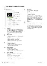
Page 42: ...previous menu change a setting that has not been confirmed D Control knob The control knob can be turned to the right or left You can scroll in menus and between options increase and decrease the values change page in multiple page instructions for example help text and service info E Switch SF1 The switch assumes three positions On Standby Emergency mode Emergency mode must only be used in the ev...

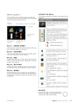
Page 43: ...ay The following symbols can appear in the display during operation Description Symbol This symbol appears by the information sign if there is information in menu 3 1 that you should note These two symbols indicate whether the compressor in the outdoor unit or addition al heat is blocked in VVM 310 Thesecan forexample beblockeddepend ing on which operating mode is selected in menu 4 2 if blocking ...

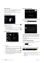
Page 44: ...the value 4 Press the OK button to confirm the value you have set To change and return to the original value press the Back button Use the virtual keyboard Different keyboards In some menus where text may require entering a virtual keyboard is available Depending on the menu you can gain access to different character sets which you can select using the control knob To change character table press ...

Page 45: ...extra help is available To access the help text 1 Use the control knob to select the help symbol 2 Press the OK button The help text often consists of several windows that you can scroll between using the control knob 45 Chapter 7 Control Introduction NIBE VVM 310 ...

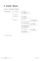
Page 46: ... 9 1 1 heating curve 1 9 1 curve 1 9 advanced 1 9 1 2 cooling curve 1 9 2 external adjustment 1 9 3 1 heating 1 9 3 min flow line temp 1 9 3 2 cooling 1 9 4 room sensor settings 1 9 5 cooling settings 1 9 6 fan return time 1 9 7 1 heating 1 9 7 own curve 1 9 7 2 cooling 1 9 8 point offset 1 9 11 Adjust Accessories are needed NIBE VVM 310 Chapter 8 Control Menus 46 8 Control Menus ...

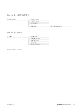
Page 47: ...ATER 2 2 comfort mode 2 3 scheduling 2 9 2 hot water recirc 2 9 advanced Menu 3 INFO 3 1 service info 3 INFO 3 2 compressor info 3 3 add heat info 3 4 alarm log 3 5 indoor temp log Accessories are needed 47 Chapter 8 Control Menus NIBE VVM 310 ...

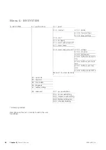
Page 48: ...4 1 8 4 tariff periods electri city 4 1 8 6 tariff per ext shunt add 4 1 8 7 tariff per ext step add 4 1 8 8 tariff periods OPT10 Menu 4 1 10 solar electricity 4 2 op mode 4 3 my icons 4 4 time date 4 6 language 4 7 holiday setting 4 9 1 op prioritisation 4 9 advanced 4 9 2 auto mode setting 4 9 3 degree minute setting 4 9 4 factory setting user 4 9 5 schedule blocking Accessory needed Description...

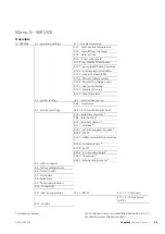
Page 49: ...s 5 3 2 shunt controlled add heat 5 3 accessory settings 5 3 3 extra climate system 5 3 4 solar heating 5 3 7 external addition 5 3 11 modbus 5 3 12 exhaust supply air module 5 3 14 F135 5 3 15 GBM communications module 5 3 16 humidity sensor 5 3 18 pool 5 3 19 active cooling 4 pipe 5 3 20 flow sensor 5 3 21 external energy meter 5 4 soft in outputs 5 5 factory setting service 5 6 forced control 5...

Page 50: ...lux 5 70 C Factory setting stop temp lux 58 C Here you set the start and stop temperature of the hot water for the different comfort options in menu 2 2 Menu 5 1 2 max flow line temperature climate system Setting range 5 70 C Default value 60 C Set the maximum supply temperature for the climate system here If the installation has more than one climate system individual maximum supply temperatures ...

Page 51: ... Menu 5 1 13 max inst el pwr BBR max installed el pwr only this machine Setting range 0 000 30 000 kW Default values 15 000 kW If the above building regulations are not applicable do not use this setting In order to meet certain building regulations it is possible to lock the device s maximum power output In this menu you can set the value corresponding to the heat pump s maximum power connection ...

Page 52: ...o the indoor module activ ate it here Menu 5 2 4 accessories Set which accessories are installed on the installation here There are two ways of activating connected accessories You can either mark the alternative in the list or use the automatic function search installed acc search installed acc Mark search installed acc and press the OK button to automatically find connected accessories for VVM 3...

Page 53: ...ol temperature Setting range 10 80 C Default value 30 C anti freeze temperature Setting range 20 20 C Default value 2 C start solar collector cooling Setting range 80 200 C Default value 110 C start delta T stop delta T Here you can set the temper ature difference between solar panel and solar tank at which the circulation pump is to start and stop max tank temperature max solar collector temp Her...

Page 54: ...stalled set the over temperature at which the bypass damper must open here months btwn filter alarms Set how often the filter alarm must be displayed See the installation instructions for ERS for function de scription Menu 5 3 14 F135 charge pump speed Setting range 1 100 Factory setting 70 hot water at cooling Setting range on off Factory setting off Here you can set the charge pump speed for F13...

Page 55: ...et including settings available to the user to default values here NOTE When resetting the start guide is displayed the next time the indoor module is restarted Menu 5 6 forced control You can force control the different components in the indoor module and any connected accessories here NOTE Forced control is only intended to be used for troubleshooting purposes Using the function in any other way...

Page 56: ...range auto intermittent Default value auto Set the operating mode for the charge pump here auto The charge pump runs according to the current operating mode for VVM 310 intermittent The charge pump starts and stops 20 seconds before and after the compressor in the heat pump speed during operation heating hot water pool cooling Setting range auto manual Default value auto Manual setting Setting ran...

Page 57: ...nstalled This allows access to country specific settings in your product Language settings can be made regardless of this selec tion NOTE This option locks after 24 hours restart of dis play or program updating 57 Chapter 8 Control Menus NIBE VVM 310 ...

Page 58: ...age 29 for instructions Emptying the hot water coil The hot water coil is most easily drained by detaching the cold water pipe at the coils s entry to the reservoir Draining the climate system In order to carry out service on the climate system it may be easier to drain the system first using drain valve QM1 NOTE There may be some hot water when draining theheatingmediumside climatesystem There is...

Page 59: ...emory This information states which product the software is intended for the software version and general informa tion about them If you wish to select another file than the one selected the correct file can be selected by choose another file start updating Select start updating if you want to start the update You are asked whether you really want to update the software Respond yes to continue or ...

Page 60: ...oggings 2 Tick activated 3 The present values from VVM 310 are saved in a file in the USB memory at the set interval until activ ated is unticked NOTE Untick activated before removing the USB memory Menu 7 3 manage settings manage settings 7 3 save settings recover settings Here you can manage save as or retrieve from all the menu settings user and service menus in VVM 310 with a USB memory Via sa...

Page 61: ...is could mean that the heat pump s compressor is not running In this case the immersion heater produces heat and or hot water NOTE To select aid mode an alarm action must be selected in the menu 5 1 4 Caution Selecting aid mode is not the same as correct ing the problem that caused the alarm The status lamp will therefore continue to be red Troubleshooting If the operational interference is not sh...

Page 62: ...ure and reduce the offset heating curve If the room temperature is only high in cold weather the curve slope in menu 1 9 1 heating curve needs adjusting down External switch for changing the room heating activ ated Check any external switches Low system pressure Not enough water in the climate system Fill the climate system with water and check for leaks see page 36 The air water heat pump s compr...

Page 63: ...iary relay HR 10 Auxiliary relay HR 10 is used to control external 1 to 3 phase loads such as oil burners immersion heaters and pumps Part no 067 309 Base extension EF 45 This accessory is used to create a larger connection area under VVM 310 Part no 067 152 Communications module MODBUS 40 MODBUS 40 enables VVM 310 to be controlled and mon itored using a DUC computer sub centre in the building Com...

Page 64: ...s used to enable connection and control of gas boiler NIBE GBM 10 15 Part no 067 513 Humidity sensor HTS 40 This accessory is used to show and regulate humidity and temperatures during both heating and cooling operation Part no 067 538 Pool heating POOL 310 POOL 310 is an accessory that enables pool heating with VVM 310 Part no 067 247 Room unit RMU 40 RMU 40 means that control and monitoring of V...

Page 65: ...Dimensions and setting out coordinates 20 1780 560 600 355 245 615 95 185 215 30 50 80 135 190 80 135 190 300 65 Chapter 12 Technical data NIBE VVM 310 12 Technical data ...

Page 66: ...50 200 250 300 350 400 450 500 Tappflöde l m Volym varmvatten liter Varmvattenkapacitet VVM310 Ekonomi Ekonomi Normal Normal Lyx Lyx Volume hot water litres Tap flow litres minute Economy Normal Lux Economy Normal Lux NIBE VVM 310 Chapter 12 Technical data 66 ...

Page 67: ...M 310 with extra additional heat for example ELK 15 15 kW Maximum connectable external additional heat 400V 3N 50Hz Rated voltage 19 4 A Maximum operating current 20 A Fuse 3 45 W Output Heating medium pump 3 45 W Output charge pump IP 21 IP class Heating medium circuit low energy Energy class circ pump low energy Energy class charge pump 0 3 3 bar MPa Maximum system pressure heating medium 70 C M...

Page 68: ...ram page 66 litre Tap volume 40 C at Economy comfort See diagram page 66 litre Tap volume 40 C at Normal comfort See diagram page 66 litre Tap volume 40 C at Lux comfort Dimensions and weight 600 mm Width 615 mm Depth 1 800 mm Height without base 1 830 1 850 mm Height with base 1 910 mm Required ceiling height 144 kg Weight excl packaging and without water 069 084 Part number EMK 310 included only...

Page 69: ...Electrical wiring diagram 3x400 V 69 Chapter 12 Technical data NIBE VVM 310 ...

Page 70: ...NIBE VVM 310 Chapter 12 Technical data 70 ...

Page 71: ...71 Chapter 12 Technical data NIBE VVM 310 ...

Page 72: ...NIBE VVM 310 Chapter 12 Technical data 72 ...

Page 73: ...73 Chapter 12 Technical data NIBE VVM 310 ...

Page 74: ...e system 58 Draining the hot water heater 58 E Electrical addition maximum output 29 Power steps of the immersion heater 29 Electrical circuit diagram 3 x 400 V 69 Electrical connections 24 28 Accessibility electrical connection 25 Cable lock 26 Communication 28 Connecting accessories 35 Connections 27 Electrical addition maximum output 29 External connection options 31 General 24 Load monitor 31 ...

Page 75: ...ers 8 Removing the hatch input circuit board 25 Room sensor 27 S Safety information 4 Inspection of the installation 6 Marking 4 Serial number 5 Symbols 4 Symbols on VVM 310 4 Scroll through the windows 44 Selecting menu 44 Selecting options 44 Serial number 5 Service 58 Service actions 58 Service actions 58 Draining the climate system 58 Draining the hot water heater 58 Standby mode 58 Temperatur...

Page 76: ......

Page 77: ......

Page 78: ......

Page 79: ...Zone industrielle RD 28 Rue du Pou du Ciel 01600 Reyrieux Tel 04 74 00 92 92 E mail info nibe fr www nibe fr FR NIBE Energy Systems Ltd 3C Broom Business Park Bridge Way S419QG Chesterfield Tel 44 0 845 095 1200 E mail info nibe co uk www nibe co uk GB NIBE Energietechniek B V Postbus 634 NL 4900 AP Oosterhout Tel 0168 477722 E mail info nibenl nl www nibenl nl NL ABK AS Brobekkveien 80 0582 Oslo ...

Page 80: ...WS name Gemensamt WS version a436 WS release date 2017 10 24 09 30 Publish date 2018 01 02 15 04 NIBE AB Sweden Hannabadsvägen 5 Box 14 SE 285 21 Markaryd info nibe se www nibe eu 231175 ...

Reviews: