Transport
VVM 310 should be transported and stored vertically in
a dry place. However, the VVM 310 may be carefully laid
on its back when being moved into a building.
Assembly
■
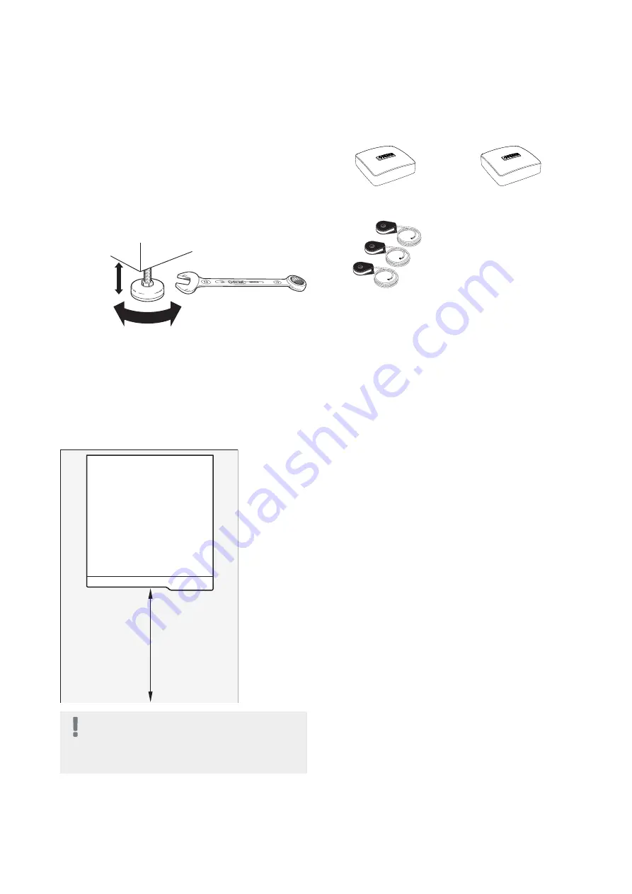
Position VVM 310 on a firm base that can take the
weight. Use the product's adjustable feet to obtain a
horizontal and stable set-up.
30 - 50 mm
30 - 50 mm
15 - 40 mm
20-55 mm
■
As water can exit the safety valve* for hot water, when
connected to VVM 310, the space where VVM 310 is
located must be provided with a floor drain.
*Not enclosed.
Installation area
Leave a free space of 800 mm in front of the product.
All service on VVM 310 can be carried out from the front.
800
NOTE
Leave 10 – 25 mm free space between the in-
door module and the wall behind for routing
of cables and pipes.
Supplied components
Room sensor
Outside sensor
LEK
LEK
LEK
Current sensor
Location
The kit of supplied items is placed on top of the product.
7
Chapter 2 |
Delivery and handling
NIBE VVM 310
2 Delivery and handling
Summary of Contents for VVM 310 EMK
Page 1: ...Installer manual APH NIBE VVM 310 EMK Indoor module IHB EN 1750 8 231175 ...
Page 69: ...Electrical wiring diagram 3x400 V 69 Chapter 12 Technical data NIBE VVM 310 ...
Page 70: ...NIBE VVM 310 Chapter 12 Technical data 70 ...
Page 71: ...71 Chapter 12 Technical data NIBE VVM 310 ...
Page 72: ...NIBE VVM 310 Chapter 12 Technical data 72 ...
Page 73: ...73 Chapter 12 Technical data NIBE VVM 310 ...
Page 76: ......
Page 77: ......
Page 78: ......


