Construction manual - Robot kit NIBO
burger
08.09.2015
2.3.5 Component placement of boards
and
Now we place components onto the both main circuit boards:
Note:
The sequence of placement depends on the height of the components
to make all soldering pads well accessible. The following subsections are
sorted according to this criterion.
2.3.5.1 Resistors
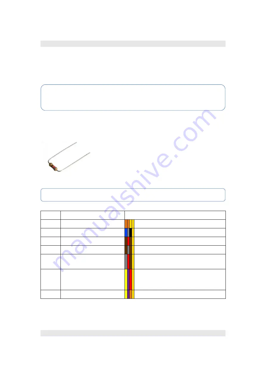
The resistors are soldered horizontal onto the
boards. The legs must be bent over, as shown in the
illustration.
You don't have to pay attention to the polarity.
The value of the resistors is indicated by a four band
colour code on the resistor, which is explained in the
appendix.
R1 – R16
are on board
,
R20 – R48
are on board
Value
Parts
Colour code
3,3 Ω
R1, R16, R40, R41, R42
orange – orange – gold - (gold)
68 Ω
R24, R25
blue – grey – black - (gold)
120 Ω R13, R14, R30, R35, R36
brown – red – brown – (gold)
180 Ω
R20, R21, R28, R29
brown – grey – brown – (gold)
820 Ω R4, R5, R6, R7, R8, R9,
R10, R11, R38, R46, R47
grey – red – brown – (gold)
4,7 kΩ R2, R3, R22, R23, R31,
R32, R33, R34, R37,
R39, R43, R44, R45
yellow – violet – red – (gold)
47 kΩ R12, R15, R26, R27, R48
yellow – violet – orange – (gold)
Tip:
There is an overview of the placement on the next pages!
http://nibo.
nicai-systems.de
42


