background image

English – 

3

1

PRODUCT DESCRIPTION AND INTENDED USE

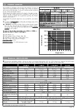
This product is destined to be used to automate gates or doors with hinged panels.

 A

TTENTION! – Any use different to that described and in environmental conditions different to those stated in this manual must 

be considered improper and prohibited!

The product is an electro-mechanical gear motor. The gear motor is powered by the external control unit, to which it must be connected.

If the electric energy is interrupted (black-out), the gate panels can be moved by releasing the gear motor using the relevant wrench; to perform 

the manual manoeuvre, see chapter

 3.

The product is available in the version:

• 

B

FAB5024 with encoder, suitable for MC824H control units

• LFAB4024 with encoder, suitable for MC824H control units

• LFAB4000 with encoder, suitable for A6F / A60 control units

• LFAB4024HS with encoder, suitable for MC824H control units

 A

TTENTION! – Do not use gear motors with incompatible control units.

2

APPLICATION LIMITS

 Caution! - The motor must be installed by qualified personnel in compliance with current legislation, standards and regulations, 

and the directions provided in this manual.

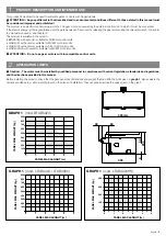
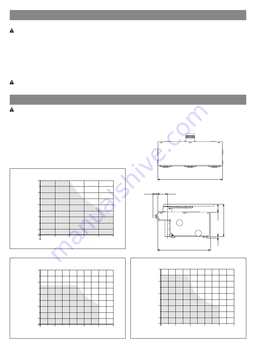
Before installing the product, check that the gate panel has dimensions and weight that lie within the limits given in


graph 1

also evaluate the 

climatic conditions (e.g. strong wind) present in the place of installation. They can greatly reduce the values given in the graph.

325

204

52

8

30

60

400 mm

100

1

2

3

4

5

200

300

400

500

600

700

900
800

GRAPH 1

  (mod. BFAB5024)

PANEL MAX WEIGHT (kg)

PANEL MAX LENGHT (m)

100

1

0

2

3

4

5

200

300

400

500

600

700

900

800

GRAPH 1

  (mod. LFAB4024 / LFAB4000)

PANEL MAX WEIGHT (kg)

PANEL MAX LENGHT (m)

1

0

2

3

4

5

100

200

300

400

GRAPH 1

  (mod. LFAB4024HS)

PANEL MAX WEIGHT (kg)

PANEL MAX LENGHT (m)

Summary of Contents for BFAB5024

Page 1: ...English 1 Nice Swing gate opener LFAB4024 LFAB4000 BFAB5024 LFAB4024HS EN Instructions and warnings for installation and use...

Page 2: ...2 English...

Page 3: ...the gearmotor 8 3 2 Manually locking the gearmotor 8 4 ELECTRICAL CONNECTIONS 9 5 AUTOMATION TESTING 9 5 1 Testing 9 5 2 Commissioning 9 6 OPTIONAL ACCESSORIES 10 7 MAINTENANCE 10 8 DISPOSAL OF THE P...

Page 4: ...and increase the risk of danger or malfunction Should this happen stop installation immediately and contact Customer Service The manufacturer assumes no liability for damage to property items or perso...

Page 5: ...th encoder suitable for A6F A60 control units LFAB4024HS with encoder suitable for MC824H control units ATTENTION Do not use gear motors with incompatible control units 2 APPLICATION LIMITS Caution Th...

Page 6: ...com ponents These components are positioned according to the typical and usual layout With reference to fig 1 establish the approximate position where each component envisioned in the plant will be in...

Page 7: ...English 5 02 Place the box inside the foundation hole the stud must be aligned with the axis of the hinge 03 Bury the foundation box in concrete making sure it is set level 1 2 24h...

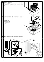
Page 8: ...previously removed washers and nuts 05 Mount the control bracket on the box s stud along with the ball Connect the gearmotor to the gate by means of the connecting lever 1 Release lever 2 Connecting l...

Page 9: ...02 Otherwise secure the opening limiter accessory to the box 1 Closing limit switch supplied with the motor 2 Opening limit switch supplied with the box 1 1 2 2 1 2 08 Fasten the cover with the screws...

Page 10: ...h and rotate it CW by 90 Follow this procedure for both gearmotors 4 3 2 1 3 2 Manually locking the gearmotor manual manoeuvre 01 Move the gate to the halfway open position by hand 02 Turn the lock co...

Page 11: ...ms for gates 5 1 Testing Each component of the system safety edges photocells emergency stop etc requires a specific testing phase To do so follow the proce dures given in the instruction manuals Run...

Page 12: ...pplies up again and run all the tests and checks described in Chapter 4 For the other equipment in the system refer to its user manuals 8 DISPOSAL OF THE PRODUCT This product is an integral part of th...

Page 13: ...f duration is strongly affected by the fatigue index of the manoeuvres performed by the automation i e the sum of all factors that contribute to wear of the product see Table 1 The estimation of durat...

Page 14: ...ordance with the provisions applicable to partly completed machinery Directive 2006 42 EC OF THE EUROPEAN PARLIAMENT AND COUNCIL of 17 May 2006 regarding machines and amending directive 95 16 EC conso...

Page 15: ...fter approximately 2 seconds the gate will start moving in the man present mode that is so long as the control is kept activated the gate will keep moving as soon as the control is released the gate w...

Page 16: ......

Reviews: