background image

Français – 

7

Français

Fuse 1.6A T

Flash

ECSbus

Aerial

Fuse 15A

P4

L4

L3

L2

P3

P2

SbS

L1

P1

Fuse 1.6A T

Flash

ECSbus

A

Fuse 

15A

Aerial

al

Sb

L4

L3

L2

P3

P2

SbS

L1

P1

L4

L3

L2

P3

P2

SbS

L1

P1

16

Fuse 1.6A T

Flash

ECSbus

Stop

Aerial

SbS

OGI

Fuse 15A

Fuse 1.6A T

Flash

Fuse 

15A

OG

OGI

ECSbus

Sbus

Stop

A

Ae

St

P3

P1

P3

P1

L2

P2

17

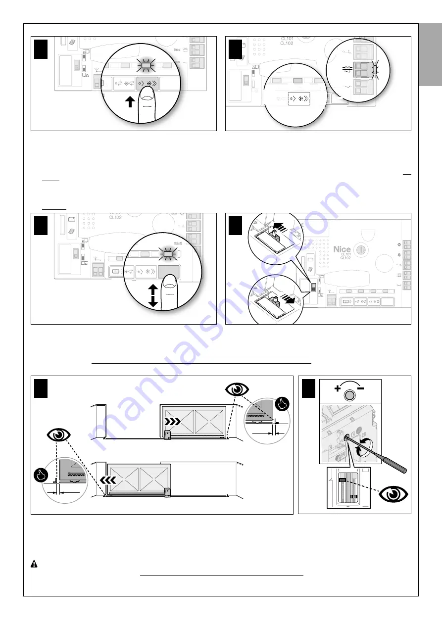
5.4 -MÉMORISATION DE LA LONGUEUR DU VANTAIL DU PORTAIL (ouverture et fermeture)

Après la reconnaissance des dispositifs 

(paragraphe 5.3), il faut faire mémoriser par la logique de commande la longueur du portail, qui est mesurée 

depuis le fin de course de fermeture jusqu’au fin de course d’ouverture. L’opération est également nécessaire pour calculer les points de ralentissement 

et le point d’ouverture partielle.

01.


Sur la logique de commande 

(

fig. 18

) appuyer et relâcher la 

touche P1

 : attendre que la logique de commande complète la manœuvre d’

ou-

verture

 jusqu’à ce que le fin de course d’ouverture soit atteint. 

Uniquement lorsque la manœuvre N’est PAS une ouverture

, procéder comme 

suit : a) appuyer et relâcher la touche P1 pour bloquer la manœuvre – b) couper l'alimentation de la logique de commande – c) déplacer le sélec

-

teur sur la logique de commande (fig. 19) – d) rebrancher l'alimentation à la logique de commande – e) appuyer et relâcher la touche P1.

02.


Sur la logique de commande 

(

fig. 19

) appuyer et relâcher la 

touche P1

 : attendre que la logique de commande complète la manœuvre 

de 

fermeture

 jusqu’à ce que le fin de course de fermeture soit atteint.

Fuse 1.6A T

Flash

ECSbus

Aerial

Fuse 15A

P4

L4

L3

L2

P2

SbS

L1

P1

Fuse 1.6A T

Flash

ECSbus

Aerial

Fuse 

15A

P4

L

4

L4

L3

L2

P2

3

L2

P2

SbS

L1

P1

18

Fuse 1.6A T

Flash

ECSbus

Stop

Aerial

SbS

OGI

Fuse 15A

L4

L3

L2

SbS

L1

Fuse 1.6A T

Flash

ECSbus

Stop

Aerial

SbS

OGI

Fuse 

15A

L4

L3

L2

SbS

L1

19

03.


Enfin, exécuter plusieurs manœuvres d’ouverture et de fermeture, en vérifiant que le vantail s’arrête à une distance d’au moins 2/3 cm des butées 

mécaniques en ouverture et en fermeture 

(

fig. 20

). Si cette distance ne correspond pas, il est possible de la modifier avec précision (pour les deux 

fins de course ou un seul), comme indiqué dans la 

fig. 21

 :


1

) envoyer une commande pour déplacer le vantail au fin de course à régler (ouverture ou fermeture) - 

2

) à l’intérieur de l’opérateur et, à l’aide de 

la clé Allen fournie, calibrer (

+/-

 ... 

-

) la vis qui régule 

la roulette, placée dans la position la plus haute

, jusqu’à ce que le vantail soit à 2/3 cm


de la butée mécanique. Éventuellement

, répéter la même opération pour l’’

autre fin de course.

2/3cm

2/3cm

20

21

5.5 - MÉMORISATION DU PREMIER ÉMETTEUR

La logique de commande comprend un récepteur radio pour émetteurs ECCO5 (différents modèles) : avant de passer au reste, il faut mémoriser le 

premier émetteur en Mode 1,voir la procédure ci-dessous.
Pour mémoriser des émetteurs supplémentaires voir le paragraphe 9.3.

 Avant d’effectuer cette procédure de mémorisation, nous recommandons de la lire et de respecter les délais indiqués.

Avec cette procédure, il est possible de mémoriser simultanément 

toutes les touches

 de l’émetteur

, en les associant automatiquement aux 

commandes indiquées dans le 

Tableau 1

 ci-après.

Un émetteur mémorisé en Mode 1 peut commander un seul automatisme.

Summary of Contents for CR502

Page 1: ...ments pour l installation et l utilisation EN Instructions and warnings for installation and use IT Istruzioni ed avvertenze per l installazione e l uso PL Instrukcje i ostrzeżenia do instalacji i użytkowania Pour portails coulissants ...

Page 2: ...rincipales phases divisées en étape pour créer l installation souhaitée étape A observer è étape B installer è étape C raccorder è étape D premier allumage de l instal lation effectué par un électricien qualifié è étape E programmer EN The pages below describe with images alone the main phases divided into steps to create the desired system Step A observe è Step B install è Step C connect è Step D...

Page 3: ...Par 3 5 1 for the relevant procedure IT Installazione con cremagliera da installare vedere fig 4 parag 3 5 1 per il procedimento PL Montaż z listwą zębatą do zamontowania patrz rys 4 punkt 3 5 1 dla działania FR Installation avec crémaillère déjà existante voir fig 5 paragraphe 3 5 2 pour la procédure EN Installation with existing rack see Fig 5 Par 3 5 2 for the relevant procedure IT Installazion...

Page 4: ...IV 40 mm 40 mm 20 30 mm 4 07 08 10 09 11 35 40 mm x 2 40 cm 02 01 03 04 06 05 40 0 50 mm mm mm mm 150 150 40 0 50 mm mm mm mm 150 150 mm 150 40 0 50 mm mm mm mm 150 150 1 2 1 2 180 ...

Page 5: ...of photocells Fig 6 Paragraph 3 6 IT Installazione fotocellule fig 6 paragrafo 3 6 PL Montaż fotokomórek rys 6 punkt 3 6 FR Installation du clignotant fig 7 paragraphe 3 7 EN Installation of photocells Fig 7 Paragraph 3 7 IT Installazione lampeggiante fig 7 paragrafo 3 7 PL Montaż lampy ostrzegawczej rys 7 punkt 3 7 FL200 ...

Page 6: ...VI 20 30 mm 5 08 10 09 11 0 0 50 mm mm mm mm 150 150 12 mm 0 0 50 mm mm mm mm 150 150 12 mm mm 150 0 0 50 mm mm mm mm 150 150 12 mm 1 2 07 35 40 mm x 2 40 cm 02 03 04 06 05 1 2 01 180 ...

Page 7: ... photocells Fig 6 Paragraph 3 6 IT Installazione fotocellule fig 6 paragrafo 3 6 PL Montaż fotokomórek rys 6 punkt 3 6 FR Installation du clignotant fig 7 paragraphe 3 7 EN Installation of photocells Fig 7 Paragraph 3 7 IT Installazione lampeggiante fig 7 paragrafo 3 7 PL Montaż lampy ostrzegawczej rys 7 punkt 3 7 FL200 ...

Page 8: ...VIII 6a 6b 1 2 3 2 1 3 Fuse 1 6A T Flash ECSbus Stop Aerial SbS SbS OGI Fuse 15A L4 L3 L2 L1 PH200 1 Led SAFE 3 2 4 Ø 5 mm 01 04 02 03 05 01 02 ...

Page 9: ...IX 7 Ø 6 mm x4 05 B Ø 6 mm x4 05 A 2 1 01 02 03 04 aerial flash 2 1 06 07 08 09 FL200 Step C ...

Page 10: ...X 8 Step C 24 V 4 W OGI NC TX RX NO Fuse 1A T Flash ECSbus Stop Aerial SbS OGI Fuse 15A L4 L3 L2 SbS L1 led Stop led SbS led ECS 2 2 1 2 3 01 02 03 ...

Page 11: ...iem pokrywy motoreduktora rys 9 można przystąpić do podłączenia innych części przewidzianych dla instalacji opcjonalnych i niedo łączonych do opakowania FR Voir le chapitre 5 pour procéder au premier allumage du système Cette phase doit être effectuée exclusivement par un électricien qualifié EN To start up the system see Chapter 5 This phase must be carried exclusively by a qualified electrician ...

Page 12: ... SERVICE 9 7 MAINTENANCE 9 8 MISE AU REBUT DU PRODUIT 9 9 INFORMATIONS COMPLÉMENTAIRES 9 9 1 RÉGLAGES AVANCÉS 10 9 1 1 Réglage des paramètres à l aide de l émetteur 10 9 1 2 Fonction Présence 10 9 1 3 Vérifier les valeurs de consigne pour chaque paramètre en utilisant l émetteur 10 9 2 AJOUT OU RETRAIT DES DISPOSITIFS 10 9 2 1 Mémorisation d autres dispositifs 10 9 3 MÉMORISATION D AUTRES ÉMETTEUR...

Page 13: ... et créer des dysfonctionnements ou des situations de danger Le cas échéant suspendre immédiatement l installation et s adresser au service après vente Le fabricant décline toute responsabilité en cas de dommages patrimoniaux causés à des biens ou à des personnes dérivant du non respect des instructions de montage Dans ces cas la garantie pour défauts matériels est exclue Le niveau de pression aco...

Page 14: ...ffisamment d espace dans la zone d installation de l opérateur pour effectuer l opération de déverrouillage manuel Vérifier que la zone de fixation de l opérateur n est pas sujette à inondation éventuellement installer l opérateur suffisamment soulevé par rapport au sol Vérifier que les surfaces d installation des différents dispositifs sont solides en vue de garantir une fixation stable et protég...

Page 15: ...caractéristiques techniques se réfèrent à la température de 20 C 3 4 TRAVAUX AVANT L INSTALLATION En s inspirant de la fig 3 déterminer l emplacement approximatif de chaque dispositif prévu dans l installation les différents éléments sont positionnés selon un schéma standardisé et habituel Procurer tous les outils et les matériaux indispensables à la réalisation des travaux Vérifier qu ils sont en...

Page 16: ...arquer son trou de mon tage lorsque la fente est située au niveau de l axe vertical du pignon Répéter cette étape pour chaque point de fixation phase 14 fig 4 15 Après avoir réglé le dernier tronçon de crémaillère s il dépasse du vantail couper l excédent phase 15 fig 4 La crémaillère ne doit pas dépasser du vantail 16 Se procurer une cale de 2 à 3 cm et la placer devant la butée mécanique phase 1...

Page 17: ...r une surface verticale Pour la procédure d installation voir la fig 7 PH200 FL200 4 RACCORDEMENTS ÉLECTRIQUES Étape C 4 1 CONNEXION ÉLECTRIQUE À LA LOGIQUE DE COMMANDE fig 8 01 Percer la membrane en caoutchouc et insérer les câbles nécessaires pour la connexion des différents dispositifs phase 01 fig 8 laisser une longueur de 40 50 cm pour les câbles et les fixer avec les attaches phase 02 fig 8 ...

Page 18: ...urs allumée 03 Si toutes ces vérifications ne sont pas conformes couper l alimentation de la logique de commande et vérifier les connexions des câbles déjà réalisés D autres informations utiles sont disponibles dans les chapitres 9 9 et 10 13 Fuse 1 6A T Flash ECSbus Stop Aerial SbS OGI Fuse 15A P4 L4 P3 P2 SbS L1 P1 Aerial Fuse 15A P4 L4 P3 P2 P1 Fus SbS L1 1 T Flash Stop SbS OGI sh Stop bS OGI E...

Page 19: ... Flash ECSbus Aerial Fuse 15A P4 L4 L3 L2 P2 SbS L1 P1 Fuse 1 6A T Flash ECSbus Aerial Fuse 15A P4 L 4 L4 L3 L2 P2 3 L2 P2 SbS L1 P1 18 Fuse 1 6A T Flash ECSbus Stop Aerial SbS OGI Fuse 15A L4 L3 L2 SbS L1 Fuse 1 6A T Flash ECSbus Stop Aerial SbS OGI Fuse 15A L4 L3 L2 SbS L1 19 03 Enfin exécuter plusieurs manœuvres d ouverture et de fermeture en vérifiant que le vantail s arrête à une distance d a...

Page 20: ...ash ECSbus A Fuse 15A Stop Aerial al Sb P4 L4 L3 L2 P3 P2 SbS L1 P1 4 L4 L3 L2 P3 P2 SbS L1 P1 23 Fuse 1 6A T Flash ECSbus Stop Aerial SbS OGI Fuse 15A P4 L4 L3 L2 P3 P2 SbS L1 P1 Fuse 1 6A T Flash ECSbus Stop SbS OGI Fuse 15A bS 1 S Sb L L1 P P1 P4 L4 L3 L2 P3 P2 P4 L4 L3 L2 P3 P2 24 semi automatique automatique 22 6 ESSAI ET MISE EN SERVICE ATTENTION L essai et la mise en service de l automatism...

Page 21: ...le vantail et en conséquence inverse le mouvement Fonction SbS séquence des déplacements du vantail associé à chaque commandes pas à pas SbS Fonction OGI Open Gate Indicator sortie à laquelle il est possible de connecter une ampoule de signalisation 24V maximum 4W Le réglage peut être effectué avec n importe quel émetteur mémorisé en Mode 1 comme ceux fournis voir paragraphe 9 3 1 S il n y a aucun...

Page 22: ... est fermé lorsque le portail est ouvert avec fermeture automatique active à la fin de la manœuvre l éclairage automatique reste allumé pendant 5 se condes puis s éteint et le comportement du portail lorsqu il est fermé reprend Si la fonction OGI est active le comportement de l ampoule qui y est connectée est le suivant éteinte automatisme dans la position de fermeture maximum clignotement lent ex...

Page 23: ...possible de mémoriser une seule touche à la fois en l associant au choix à l une des commandes indiquées dans le Tableau 5 Un émetteur mémorisé en Mode 2 peut commander plusieurs automatismes par exemple automatisme 1 commandé par la touche 1 automatisme 2 commandé par la touche 2 et ainsi de suite TABLEAU 5 Procédure de mémorisation 01 Avant de procéder il faut effacer la mémoire de l émetteur à ...

Page 24: ...e 02 Lorsque la led L4 s allume toujours en maintenant enfoncée la touche P4 appuyer et maintenir enfoncée aussi la touche de l émetteur à effacer jusqu à ce que la led L4 effectue 5 clignotements rapides puis relâcher les deux touches Répéter cette procédure pour chaque émetteur à effacer 9 5 EFFACEMENT TOTAL DE LA MÉMOIRE RADIO Cette procédure permet d effacer TOUS les émetteurs mémorisés procéd...

Page 25: ...on 8 12 Vcc est présente si la tension est correcte la photocellule est probablement en panne 3 clignotements rapides et 1 seconde de pause Dispositif non reconnu par la logique de commande Répéter la procédure de reconnaissance sur l a logique de commande Vérifier que toutes les paires de photocellules sur ECSBus ont des adresses différentes voir la notice des photocellules 1 clignotement très le...

Page 26: ...Sbs 9 clignotements pause de 1 seconde 9 clignotements L automatisme est bloqué Débloquer l automatisme en envoyant la commande de déblocage de l automa tisme à la logique de commande 9 10 3 Signalisations de la logique de commande La logique de commande présente des led fig 8 émettant des signaux aussi bien en fonctionnement normal qu en cas d anomalies voir le Tableau 8 TABLEAU 8 Led ECSBus État...

Page 27: ... ils sont de différents types voir le Tableau 9 TABLEAU 9 Remarque 1 il est possible de combiner NO et NF en mettant les deux contacts en parallèle en prenant la précaution de mettre en série au contact NF une résistance de 8 2 kΩ il est donc possible de combi ner 3 dispositifs NO NF et 8 2 kΩ Remarque 2 plusieurs dispositifs NO peuvent être connectés entre eux en parallèle sans aucune limite de q...

Page 28: ... pas et la led ECS Bbus ne clignote pas sur la logique de com mande Vérifier que le câble d ali mentation est correctement branché dans la prise du secteur Vérifier si les fusibles sont intervenus S ils sont inter venus s assurer de la cause de la panne puis les rempla cer par d autres de la même valeur voir fig 33 fuse 3 15A T fuse 1A T 33 La manœuvre ne démarre pas et le cligno tant de l automat...

Page 29: ...courant ou d anomalies de l installation Dans le cas d une panne de courant il est égale ment possible d utiliser une batterie tampon mod PR100 non fourni voir Chapitre 9 Approfondissement ou notice correspondante En cas de panne de l opérateur il est tout de même possible d essayer d utiliser le débrayage du moteur pour vérifier si la panne ne concerne pas le mécanisme de débrayage 180 180 11 3 I...

Page 30: ......

Page 31: ...ée de fabrication Lieu d installation adresse Satisfait les exigences essentielles des directives suivantes 2006 42 CE Directive Machines et ce qui est prévu par les normes harmonisées suivantes EN 12445 Portes et portails équipant les locaux industriels et commerciaux et les garages Sécurité dans l utilisation de portes motorisées Méthodes d essai EN 12453 Portes et portails équipant les locaux i...

Page 32: ...ISSIONING 9 7 MAINTENANCE 9 8 PRODUCT DISPOSAL 9 9 FURTHER INFORMATION 9 9 1 ADVANCED ADJUSTMENTS 10 9 1 1 Adjusting the parameters using the transmitter 10 9 1 2 Presence function 10 9 1 3 Verifying the values set for each parameter using the transmitter 10 9 2 ADDING OR REMOVING DEVICES 10 9 2 1 Memorising additional devices 10 9 3 MEMORISING ADDITIONAL TRANSMITTERS 11 9 3 1 Mode 1 memorisation ...

Page 33: ...m sources of heat and open flames Failure to observe the above can damage the product and increase the risk of danger or malfunctions If this should happen stop installation immediately and contact the Customer Service The manufacturer assumes no liability for damage to property items or persons resulting from non compliance with the assembly instructions In such cases the warranty does not cover ...

Page 34: ...ient space where the gearmotor is installed to allow for effecting a manual release manoeuvre Make sure that the area where the gearmotor is secured is not subject to flooding if necessary mount the gearmotor adequately raised from the ground Check that the installation surfaces of the various devices are solid for guaranteeing a stable anchorage and that they are protected and guarded against acc...

Page 35: ...ations refer to a temperature of 20 C 3 4 PRE INSTALLATION WORKS Consult Fig 3 to define the approximate installation position of each device mounted on the system the various elements are positioned according to a standard and customary layout Get all the tools and equipment required to complete the job check that they are in good condition and that they conform to the local safety provisions Lay...

Page 36: ...st part of the rack if it protrudes from the gate cut the part in excess Phase 15 Fig 4 The rack must not pro trude from the gate 16 Take a 2 3 cm spacer and place it in front of the mechanical stop Phase 16 Fig 4 then manually move the gate towards the mechanical stop while making it lie on the spacer When moving the gate make sure that the rack slides regularly over the pinion 17 Manually lock t...

Page 37: ...O THE CONTROL UNIT Fig 8 01 Perforate the rubber membrane and insert the cables necessary to connect the various devices Phase 01 Fig 8 leave the cables at least 40 50 cm long and secure them with cable ties Phase 02 Fig 8 02 Connect the various devices of the kit and any other components designed for being used on the system optional and not included in the pack age Phase 03 Fig 8 It is not neces...

Page 38: ...non conforming disconnect the power supply to the control unit and check the relevant connections of the cables Other useful information is contained in Chapters 9 9 and 10 13 Fuse 1 6A T Flash ECSbus Stop Aerial SbS OGI Fuse 15A P4 L4 P3 P2 SbS L1 P1 Aerial Fuse 15A P4 L4 P3 P2 P1 Fus SbS L1 1 T Flash Stop SbS OGI sh Stop bS OGI ECSbus 14 led SAFE TX RX 15 5 3 MEMORISATION OF CONNECTED DEVICES On...

Page 39: ...use 1 6A T Flash ECSbus Aerial Fuse 15A P4 L 4 L4 L3 L2 P2 3 L2 P2 SbS L1 P1 18 Fuse 1 6A T Flash ECSbus Stop Aerial SbS OGI Fuse 15A L4 L3 L2 SbS L1 Fuse 1 6A T Flash ECSbus Stop Aerial SbS OGI Fuse 15A L4 L3 L2 SbS L1 19 03 Lastly perform various opening and closing manoeuvres while checking that the gate leaf stops at least 2 3 cm from the mechanical stops during both the opening and closing ph...

Page 40: ...a Fig 24 Fuse 1 6A T Flash ECSbus Stop Aerial Fuse 15A P4 L4 L3 L2 P3 P2 SbS L1 P1 Fuse 1 6A T Flash ECSbus A Fuse 15A Stop Aerial al Sb P4 L4 L3 L2 P3 P2 SbS L1 P1 4 L4 L3 L2 P3 P2 SbS L1 P1 23 Fuse 1 6A T Flash ECSbus Stop Aerial SbS OGI Fuse 15A P4 L4 L3 L2 P3 P2 SbS L1 P1 Fuse 1 6A T Flash ECSbus Stop SbS OGI Fuse 15A bS 1 S Sb L L1 P P1 P4 L4 L3 L2 P3 P2 P4 L4 L3 L2 P3 P2 24 semi automatic au...

Page 41: ...ly inverts the direction of movement SbS Function sequence of gate movements associated with the Step by Step SbS command OGI Open Gate Indicator function output to which it is possible to connect a 24 V maximum 4 W warning light The adjustment can be effected by means of any transmitter memorised in Mode 1 as those supplied see Paragraph 9 3 1 If there is no transmitter memorised in Mode 1 it is ...

Page 42: ... light remains lit for 5 seconds then switches off and follows the gate s behaviour when closed If the OGI function is active the lamp connected to it behaves in the following way off automation in fully closed position slow flashing execution of the opening manoeuvre fast flashing execution of the closing manoeuvre steady lit automation in fully open position 9 1 3 Verifying the values set for ea...

Page 43: ...r 9 4 02 In Table 5 choose the command and the number of press down actions to be effected on the desired transmitter key 03 On the control unit Fig 28 press and release button P4 for a number of times corresponding to the chosen command Table 5 led L4 must emit a number of fast flashes corresponding to the chosen command 04 Within 10 seconds press and hold for 2 seconds the key of the transmitter...

Page 44: ...ed 9 5 COMPLETE DELETION OF THE RADIO MEMORY This procedure allows for cancelling ALL memorised transmitters the procedure must be carried out on the control unit before proceeding open the cover of the gearmotor Fig 9 01 On the control unit Fig 28 press and hold button P4 02 Check that led L4 lights up for 4 5 seconds that it switches off then flashes 3 times 03 Precisely at the 3rd flash release...

Page 45: ...eck that the voltage on the photocell terminals is around 8 12 VDC if the volt age is correct the photocell is probably faulty 3 quick flashes and 1 second pause Device not recognised by the control unit Repeat the recognition procedure on the control unit Check that all pairs of pho tocells on the ECSBus have different addresses consult the instruction manual of the photocells 1 very slow flash T...

Page 46: ...is locked Release the automation by sending an automation release command to the con trol unit 9 10 3 Control unit signals On the control unit there are LEDs Fig 8 that emit signals both during normal operation and in case of anomalies see Table 8 TABLE 8 Led ECSBus Status Action Off Fault Verify whether there is power and whether the fuses are blown in this case iden tify the reason for the failu...

Page 47: ... can be connected in parallel to each other without any quantity limit Note 3 multiple NC devices can be connected in series to each other without any quantity limit Note 4 only 2 devices with 8 2 kΩ constant resistance output can be connected in parallel if required multiple devices must be connected in cascade mode with a single 8 2 kΩ termination resistance 2 nd type device 1st type device NO N...

Page 48: ...e of the fault and replace them with others of the same type see Fig 33 fuse 3 15A T fuse 1A T 33 The manoeuvre fails to start and the auto mation s flashing light is off Check that the command is actually received If the command reaches the SbS input the rel evant SbS Led lights up if a transmitter is used the ECSBus Led must emit 2 long flashes The manoeuvre fails to start and the auto mation s ...

Page 49: ...ng the system In case of a power outage a back up battery can be used model PR100 not supplied see Chapter 9 Further information or the relevant instruction manual In the event of a gearmotor fault it is still possible to try release the motor to check whether the fault lies in the release mechanism 180 180 11 3 User admissible maintenance operations The operations that the user must carry out per...

Page 50: ......

Page 51: ...tion motor driven sliding gate Serial N Year of manufacture Location address Complies with the essential requirements of the following directives 2006 42 EC Machines Directive and as provided for in the following harmonised standards EN 12445 Industrial commercial and garage doors and gates Safety in use of Power operated doors and gates Test Methods EN 12453 Industrial commercial and garage doors...

Page 52: ...UTENZIONE 9 8 SMALTIMENTO DEL PRODOTTO 9 9 APPROFONDIMENTI 9 9 1 REGOLAZIONI AVANZATE 10 9 1 1 Regolazione dei parametri usando il trasmettitore 10 9 1 2 Funzione Presenza 10 9 1 3 Verifica dei valori impostati per ciascun parametro usando il trasmettitore 10 9 2 AGGIUNTA O RIMOZIONE DEI DISPOSITIVI 10 9 2 1 Memorizzazione di ulteriori dispositivi 10 9 3 MEMORIZZAZIONE DI ULTERIORI TRASMETTITORI 1...

Page 53: ...situazioni di pericolo Se questo accade sospendere immediatamente l installazione e rivolgersi al Servizio Assistenza Il produttore non si assume alcuna responsabilità per danni patrimoniali a cose o a persone derivanti dalla non osservanza delle istruzioni di mon taggio In questi casi è esclusa la garanzia per difetti materiali Il livello di pressione acustica dell emissione ponderata A è inferio...

Page 54: ...uttore ci sia lo spazio sufficiente per effettuare la manovra manuale di sblocco Verificare che la zona di fissaggio del motoriduttore non sia soggetta ad allagamenti eventualmente installare il motoriduttore adeguatamente solle vato da terra Verificare che le superfici d installazione dei vari dispositivi siano solide per garantire un fissaggio stabile e che siano protette e al riparo da urti acc...

Page 55: ...LIMINARI ALL INSTALLAZIONE Prendendo spunto dalla fig 3 stabilire la posizione approssimativa d installazione di ogni dispositivo previsto nell impianto i vari elementi sono posi zionati secondo uno schema standard ed usuale Procurare tutti gli attrezzi e i materiali indispensabili per la realizzazione del lavoro verificare che siano in buone condizioni e conformi a quanto previsto dalle normative...

Page 56: ...se verticale del pignone Ripetere questa operazione per ogni punto di fissaggio fase 14 fig 4 15 Dopo aver fissato l ultimo pezzo di cremagliera se questo sporge dall anta tagliare la parte eccedente fase 15 fig 4 La cremagliera non deve sporgere dall anta 16 Procurarsi uno spessore di 2 3 cm e posizionarlo davanti al fermo meccanico fase 16 fig 4 poi muovere manualmente l anta verso il fermo mecc...

Page 57: ...cale Per la procedura d installazione vedere fig 7 PH200 FL200 4 COLLEGAMENTI ELETTRICI Step C 4 1 COLLEGAMENTO ELETTRICO ALLA CENTRALE fig 8 01 Forare la membrana di gomma e inserire i cavi necessari per al collegamento dei vari dispositivi fase 01 fig 8 lasciare i cavi lunghi almeno 40 50 cm e fissarli con delle fascette fase 02 fig 8 02 Collegare i vari dispositivi del kit ed altri eventuali co...

Page 58: ...empre acceso 03 Se tutte queste verifiche non sono conformi togliere l alimentazione alla centrale e verificare i collegamenti dei cavi già eseguiti Altre indicazioni utili sono contenute nei capitoli 9 9 e 10 13 Fuse 1 6A T Flash ECSbus Stop Aerial SbS OGI Fuse 15A P4 L4 P3 P2 SbS L1 P1 Aerial Fuse 15A P4 L4 P3 P2 P1 Fus SbS L1 1 T Flash Stop SbS OGI sh Stop bS OGI ECSbus 14 led SAFE TX RX 15 5 3...

Page 59: ...1 Fuse 1 6A T Flash ECSbus Aerial Fuse 15A P4 L 4 L4 L3 L2 P2 3 L2 P2 SbS L1 P1 18 Fuse 1 6A T Flash ECSbus Stop Aerial SbS OGI Fuse 15A L4 L3 L2 SbS L1 Fuse 1 6A T Flash ECSbus Stop Aerial SbS OGI Fuse 15A L4 L3 L2 SbS L1 19 03 Infine eseguire varie manovre di apertura e chiusura verificando che l anta si fermi ad una distanza di almeno 2 3 cm dagli arresti meccanici sia in apertura sia in chiusu...

Page 60: ...a fig 24 Fuse 1 6A T Flash ECSbus Stop Aerial Fuse 15A P4 L4 L3 L2 P3 P2 SbS L1 P1 Fuse 1 6A T Flash ECSbus A Fuse 15A Stop Aerial al Sb P4 L4 L3 L2 P3 P2 SbS L1 P1 4 L4 L3 L2 P3 P2 SbS L1 P1 23 Fuse 1 6A T Flash ECSbus Stop Aerial SbS OGI Fuse 15A P4 L4 L3 L2 P3 P2 SbS L1 P1 Fuse 1 6A T Flash ECSbus Stop SbS OGI Fuse 15A bS 1 S Sb L L1 P P1 P4 L4 L3 L2 P3 P2 P4 L4 L3 L2 P3 P2 24 semiautomatico au...

Page 61: ...ose che se disperse nell ambiente potrebbero provocare effetti dannosi sull ambiente stesso e sulla salute umana Come indicato dal simbolo a lato è vietato gettare questo prodotto nei rifiuti domestici Eseguire quindi la raccolta separata per lo smaltimento secondo i metodi previsti dai regolamenti vigenti sul vostro territorio oppure riconsegnare il prodotto al venditore nel momento dell ac quist...

Page 62: ...matica attiva al termine della manovra la luce di cortesia rimane accesa per 5 secondi poi si spegne e riprende il comportamento del cancello quando è chiuso Se la funzione OGI è attiva il comportamento della lampada collegata ad essa è il seguente spenta automazione in posizione di massima chiusura lampeggio lento esecuzione manovra di apertura lampeggio veloce esecuzione manovra di chiusura acce...

Page 63: ...a dal tasto 1 automazione 2 comandata dal tasto 2 e cosi via TABELLA 5 Procedura di memorizzazione 01 Prima di procedere è necessario cancellare la memoria del trasmettitore da memorizzare vedere parag 9 4 02 Nella Tabella 5 sceglere il comando e il numero di pressioni da eseguire sul tasto desiderato del trasmettitore 03 Sulla centrale fig 28 premere e rilasciare il tasto P4 il numero di volte pa...

Page 64: ...i tasti Ripetere la procedura per ogni trasmettitore da cancellare 9 5 CANCELLAZIONE TOTALE DELLA MEMORIA RADIO Questa procedura permette di cancellare TUTTI i trasmettitori memorizzati procedura da eseguire sulla centrale prima di procedere è necessario aprire il coperchio del motoriduttore fig 9 01 Sulla centrale fig 28 premere e mantenere premuto il tasto P4 02 Verificare che il led L4 si accen...

Page 65: ... guasta Verificare che sui morsetti della fotocellula sia presente una tensione di circa 8 12 Vdc se la tensione è corretta è probabile che la fotocellula sia guasta 3 lampeggi veloci e 1 secondo di pausa Dispositivo non appreso dalla centrale Ripetere la procedura di apprendimento sulla centrale Verificare che tutte le cop pie di fotocellule su ECSBus abbiano indirizzi diversi vedere manuale d is...

Page 66: ...e è bloccata Sbloccare automazione fornendo alla centrale un comando di sblocca automa zione 9 10 3 Segnalazioni della centrale di comando Sulla centrale sono presenti dei led fig 8 che emettono segnalazioni sia durante il funzionamento normale sia in caso di anomalia vedere Tabella 8 TABELLA 8 Led ECSBus Stato Azione Spento Anomalia Verificare se c è alimentazione che i fusibili non siano interve...

Page 67: ...anche di tipo diverso leggere la Tabella 9 TABELLA 9 Nota 1 la combinazione NA ed NC è possibile mettendo i 2 contatti in parallelo con l avvertenza di mettere in serie al contatto NC una resistenza da 8 2kΩ è quindi possibile anche la combinazione di 3 dispositivi NA NC e 8 2kΩ Nota 2 più dispositivi NA si possono collegare in parallelo tra di loro senza alcun limite di quantità Nota 3 più dispos...

Page 68: ... trasmettitore La manovra non parte e sulla centrale il led ECSBbus non lampeggia Accertarsi che il cavo di alimentazione sia inserito correttamente nella presa della rete elettrica Verificare se sono interve nuti i fusibili se sono inter venuti accertare la causa del guasto e poi sostituirli con altri dello stesso valore vedere fig 33 fuse 3 15A T fuse 1A T 33 La manovra non parte ed il lampeggia...

Page 69: ...eve essere eseguita nel caso di mancanza di corrente o di anomalie dell impianto Nel caso di mancanza di corrente è anche possibile utilizzare una batteria tampone mod PR100 non in dotazione vedere cap 9 Approfondimenti o il rispettivo manuale d istruzione In caso di guasto al motoriduttore è comunque possibile provare ad utilizzare lo sblocco del motore per verificare se il guasto non risiede nel...

Page 70: ......

Page 71: ...ne cancello scorrevole motorizzato Matricola N Anno di fabbricazione Ubicazione indirizzo Soddisfa i requisiti essenziali delle seguenti direttive 2006 42 CE Direttiva Macchine e quanto previsto dalle seguenti norme armonizzate EN 12445 Porte e cancelli industriali commerciali e da autorimessa Sicurezza in uso di porte motorizzate Metodi di prova EN 12453 Porte e cancelli industriali commerciali e...

Page 72: ...LOATACJI 9 7 KONSERWACJA 9 8 UTYLIZACJA PRODUKTU 9 9 INFORMACJE DODATKOWE 9 9 1 REGULACJE ZAAWANSOWANE 10 9 1 1 Regulacja parametrów przy użyciu nadajnika 10 9 1 2 Funkcja obecności 10 9 1 3 Kontrola wartości ustawionych dla każdego parametru przy użyciu nadajnika 10 9 2 DODAWANIE LUB USUWANIE URZĄDZEŃ 10 9 2 1 Wczytywanie kolejnych urządzeń 10 9 3 WCZYTYWANIE KOLEJNYCH NADAJNIKÓW 11 9 3 1 Procedu...

Page 73: ...o ognia Opisane powyżej sytu acje mogą doprowadzić do uszkodzenia urządzenia być przyczyną nieprawidłowego działania lub zagrożeń Jeżeli doszłoby do którejś z opisanych sytuacji należy natychmiast przerwać montaż i zwrócić się o pomoc do Serwisu Technicznego Producent nie ponosi odpowiedzialności za szkody materialne lub osobowe powstałe w wyniku nieprzestrzegania instrukcji montażu W takich przyp...

Page 74: ...wisku w którym ma być zainstalowany motoreduktor istnieje wystarczająca ilość miejsca na wykonanie manewru ręcznego odblokowania Sprawdzić strefę mocowania motoreduktora czy nie jest narażona na zalanie i w razie konieczności zapewnić montaż ponad podłożem Sprawdzić czy powierzchnie montażowe różnych urządzeń są wystarczająco mocne aby zapewnić stabilne mocowanie i czy są chronione i osło nięte pr...

Page 75: ... KONTROLE WSTĘPNE PRZED MONTAŻEM Na podstawie rys 3 ustalić przybliżoną pozycję montażową każdego urządzenia wchodzącego w skład instalacji różne elementy są rozmieszczone zgodnie ze standardowym Przygotować wszystkie narzędzia i materiały konieczne do wykonania prac sprawdzić czy są one w dobrym stanie i czy są zgodne z lokalnymi prze pisami bezpieczeństwa Przygotowanie kabli elektrycznych 01 Pat...

Page 76: ...ębatej w pozycji poziomej należy zaznaczyć otwór mocujący gdy otwór znajduje się na wysokości pionowej osi koła zębatego Powtórzyć to działanie w każdym punkcie mocowania faza 14 rys 4 15 Jeżeli jest to konieczne po przymocowaniu ostatniego elementu listwy mocującej odciąć wystającą część faza 15 rys 4 Listwa zębata nie może wystawać ze skrzydła 16 Przygotować element dystansowy o grubości 2 3 cm ...

Page 77: ...sposób wskazany na rys 8 Wybrać najbardziej odpowiednią pozycję w której zamontować lampę ostrzegawczą należy ją umieścić w pobliżu bramy i musi być ona łatwo dostrze galna Istnieje możliwość jej zamontowania lampy na powierzchni pionowej lub poziomej W celu uzyskania informacji na temat procedury montażu patrz rys 7 PH200 FL200 4 POŁĄCZENIA ELEKTRYCZNE Krok C 4 1 PODŁĄCZENIE ELEKTRYCZNE DO CENTRA...

Page 78: ...sze zgaszona 03 Jeżeli te kontrole nie dadzą pozytywnego wyniku zaleca się odłączyć zasilanie od centrali i sprawdzić podłączenie kabli Inne użyteczne informacje zostały zamieszczone w rozdziale 9 9 i 10 13 Fuse 1 6A T Flash ECSbus Stop Aerial SbS OGI Fuse 15A P4 L4 P3 P2 SbS L1 P1 Aerial Fuse 15A P4 L4 P3 P2 P1 Fus SbS L1 1 T Flash Stop SbS OGI sh Stop bS OGI ECSbus 14 led SAFE TX RX 15 5 3 WCZYT...

Page 79: ...L4 L3 L2 P2 3 L2 P2 SbS L1 P1 18 Fuse 1 6A T Flash ECSbus Stop Aerial SbS OGI Fuse 15A L4 L3 L2 SbS L1 Fuse 1 6A T Flash ECSbus Stop Aerial SbS OGI Fuse 15A L4 L3 L2 SbS L1 19 03 Na koniec należy wykonać różne manewry otwierania i zamykania upewniając się że skrzydło zatrzyma się w odległości przynajmniej 2 3 cm od ograniczników mechanicznych zarówno podczas otwierania jak i podczas zamykania rys ...

Page 80: ...ego na automatyczny i vice versa rys 24 Fuse 1 6A T Flash ECSbus Stop Aerial Fuse 15A P4 L4 L3 L2 P3 P2 SbS L1 P1 Fuse 1 6A T Flash ECSbus A Fuse 15A Stop Aerial al Sb P4 L4 L3 L2 P3 P2 SbS L1 P1 4 L4 L3 L2 P3 P2 SbS L1 P1 23 Fuse 1 6A T Flash ECSbus Stop Aerial SbS OGI Fuse 15A P4 L4 L3 L2 P3 P2 SbS L1 P1 Fuse 1 6A T Flash ECSbus Stop SbS OGI Fuse 15A bS 1 S Sb L L1 P P1 P4 L4 L3 L2 P3 P2 P4 L4 L...

Page 81: ...zne które pozostawione w środowisku mogłyby zaszkodzić środowisku lub zdrowiu ludzkiemu Jak wskazuje symbol obok zabrania się wyrzucania niniejszego produktu razem z odpadami domowymi W celu usunięcia produktu należy zatem przeprowadzić zgodnie z lokalnie obowiązującymi przepisami zbiórkę selektywną lub zwrócić produkt do sprzedawcy w chwili zaku pu nowego równoważnego produktu Uwaga lokalne przep...

Page 82: ...rametru przy użyciu nadajnika wczytanego w trybie 1 Kontrola może się odbywać za pomocą każdego nadajnika wczytanego w Trybie 1 jak dołączone nadajniki patrz punkt 9 3 1 Jeśli nie jest dostępny żaden nadajnik wczytany w Trybie 1 można wczytać jeden nadajnik wyłącznie w celu wykonania programowania i następnie go skasować patrz punkt 9 4 Procedura regulacji przed rozpoczęciem sprawdzić w Tabeli 3 p...

Page 83: ...nia w ciągu kolejnych 10 s powtó rzyć Krok 03 w przeciwnym razie procedura wczytywania zakoń czy się automatycznie L naciśnięć przycisku Polecenie przypisane L mignięć diody L4 na centrali 1 raz Krok po kroku 1 2 razy Otwarcie dla pieszych 2 3 razy Tylko otwiera 3 4 razy Tylko zamyka 4 5 razy Wyjście Light 230V On Off 5 6 razy Stop 6 7 razy Otwórz zespół mieszkalny 7 8 razy Otwórz Wysoki priorytet...

Page 84: ...łań należy otworzyć pokrywę motoreduktora rys 9 01 Na centrali rys 28 nacisnąć i przytrzymać wciśnięty przycisk P4 02 Sprawdzić czy dioda L4 zaświeci się na4 5 sekund a następnie zgaśnie i wykona 3 mignięcia 03 Dokładnie w chwili 3 mignięcia zwolnić przycisk P4 04 Sprawdzić czy dioda L4 wykona bardzo szybkie mignięcia 05 Sprawdzić czy dioda L4 wykona 5 wolnych mignięć skasowanie wykonane 9 6 MONTA...

Page 85: ...Vdc jeżeli napięcie jest prawidłowe prawdopodobnie fotokomórka jest uszkodzona 3 szybkie mignięcia i 1 sekunda przerwy Urządzenie nie zostało rozpoznane przez centralę Powtórzyć procedurę wczytywania centrali Sprawdzić czy wszystkie pary foto komórek na ECSBus mają różne adresy patrz instrukcja obsługi fotokomórek 1 mignięcie bardzo wolne Odbiornik odbiera optymalny sygnał Prawidłowe funkcjonowani...

Page 86: ...ć Automatyka jest zablokowana Odblokować automatykę wydając centrali polecenie odblokowania automa tyki 9 10 3 Sygnalizacja centrali sterującej Na centrali sterującej są obecne diody rys 8 emitujące sygnalizacje zarówno podczas normalnego funkcjonowania jak i w razie anomalii patrz Tabela 8 TABELA 8 Led ECSBus Stan Działanie Zgaszona Anomalia Sprawdzić czy występuje zasilanie Sprawdzić czy nie zad...

Page 87: ...ć podłączenia do wejścia Stop więcej niż jednego urządzenia nawet różnych rodzajów patrz Tabela 9 TABELA 9 Uwaga 1 kombinację NO i NC otrzymamy łącząc te 2 pary styków równolegle i dołączając szeregowo ze stykiem NC opór 8 2kΩ możliwa jest zatem kombinacja 3 urządzeń NO NC i 8 2 kΩ Uwaga 2 równolegle między sobą może być połączona dowolna liczba urządzeń typu NO Uwaga 3 równolegle między sobą może...

Page 88: ...a się ale zaraz po tym następuje odwrócenie ruchu bramy Wybrana siła silnika jest zbyt mała aby poruszać bramą Sprawdzić czy występują jakieś prze szkody uniemożliwiające ruch i ewentualnie wybrać większą siłę zgodnie z opisem w punkcie 9 1 1 Manewr jest wykonywany ale nie działa lampa ostrzegawcza Sprawdzić czy podczas manewru występuje napięcie na zacisku Flash lampy ostrzegawczej ponieważ jest ...

Page 89: ...prądu można również używać akumulatora awaryjnego mod PR100 nieznajdujące się na wyposażeniu patrz rozdz 9 Informacje dodatkowe lub odpowiednia instrukcja obsługi W przypadku awarii motoreduktora możliwe jest wykonanie odblokowania silnika w celu sprawdzenia czy usterka nie dotyczy mechanizmu odbloko wującego 180 180 11 3 Konserwacja do wykonania przez użytkownika Poniżej wymienione zostały czynno...

Page 90: ......

Page 91: ...ama przesuwna z napędem Nr seryjny Rok produkcji Lokalizacja adres Spełnia podstawowe wymogi następujących dyrektyw 2006 42 WE Dyrektywa Maszynowa Jest również zgodna z następującymi normami zharmonizowanymi EN 12445 Drzwi i bramy przemysłowe handlowe i garażowe Bezpieczeństwo użytkowania bram z napędem metody badań EN 12453 Drzwi i bramy przemysłowe handlowe i garażowe Bezpieczeństwo użytkowania ...

Page 92: ...8 juillet 2016 Ing Roberto Griffa Administrateur délégué EC Declaration of Conformity Declaration in accordance with the following Directives 1995 5 EC R TTE 2014 30 EU EMC 2006 42 EC MD Annex II Part B Note The contents of this declaration correspond to that stated in the official document filed in the offices of Nice S p A and in particular the latest version thereof available prior to the print...

Page 93: ...cutive Officer Dichiarazione CE di conformità Dichiarazione in accordo alle Direttive 1995 5 CE R TTE 2014 30 UE EMC 2006 42 CE MD allegato II parte B Nota Il contenuto di questa dichiarazione corrisponde a quanto dichiarato nel documento ufficiale depositato presso la sede di Nice S p a e in particolare alla sua ultima revisione disponibi le prima della stampa di questo manuale Il testo qui prese...

Page 94: ......

Page 95: ......

Page 96: ... com Service Après Vente France En cas de panne merci de contacter obligatoirement notre Service Après Vente par téléphone ou par email 0 820 859 203 Service 0 15 min prix appel niceservice niceforyou com Merci de ne pas retourner le produit en magasin Worldwide Customer Service customerservice niceforyou com ...

Reviews: