background image

3

- The quality of the radio signal received can be checked on the control unit dis-

play (see paragraph 9.2.5 “FIELD METER test”) and if in doubt, test before fix-
ing the control unit to the wall. In the case of radio appliances, a change in
position of even just a few centimetres can significantly improve signal recep-
tion and transmission.

- The control units are equipped with a keypad that enables programming dur-

ing installation and daily use of a number of functions, such as activation/ dea-
ctivation of the alarm. If these functions are required, the control unit must be
located in an accessible position, normally close to the main entrance door.

- If a connection to the telephone line is required, ensure that the relative hook-

up is feasible.

- The control units with mains power must be positioned where the relative

electrical connection is possible.

• Keypads

For aesthetic reasons or due to electrical connection requirements, if the con-
trol unit has to be positioned far from the main entrance door, a keypad should
be installed in the vicinity.
If there are other entrance points to the home, a keypad should be installed at
each access point. The keypads can be wall-mounted or portable (as with a
transmitter) if required.

• 

Sirens

In the case of isolated buildings, the installation of at least one outdoor siren is
strongly recommended. This should be positioned in a highly visible location (to
aid as a deterrent) but in a place difficult to access by vandals/burglars.  
Although the sirens are adequately protected for outdoor applications, they
should be installed in an area protected against direct rain; the ideal location
would be under a protruding roof or on a terrace/balcony.
The control unit has an incorporated siren, but in large or multi-floor buildings,
the addition of one or more indoor sirens is recommended, located in the main
rooms.
In small apartments, or densely populated areas, an outdoor siren may not be
welcome; in this case, one or more indoor sirens may be used to increase the
deterrent effect.

• Sensors

The choice of the type of sensor to be used is fundamental, as is the relative
position of installation: an incorrect sensor or one positioned in an unsuitable
location may not detect intrusion or may generate improper alarm signals. Each
type of sensor has a different operating principle; refer to the correct selection
criteria for each sensor in 

Table 3

.

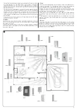
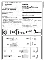
HSDID11

HSDID11

HSDID11

HSDID11

HSDIM11

HSDIM11

HSDIM12

HSDIM12

HSDIM12

HSDIS01

HSDIM21

HSDIM22

HSDOM21

HSSI

HSDIW01

HSDIW01

HSCU1GC

HSCU1C

HSCU1G

HSCU1

HSSOC

HSSO

5

Summary of Contents for HSCU1

Page 1: ...Nice HSCU1 Instructions and warnings for installation and use Home security control unit 0682 ...

Page 2: ......

Page 3: ...del HSDIM11 15 4 7 Infrared detector with vertical curta in lens model HSDIM12 16 4 8 Volumetric detector of glass breakage model HSDID01 17 4 9 Fine combustion powder detector model HSDIS01 17 4 10 Flooding detector model HSDIW01 18 4 11 4 channel alarm transmitter model HSTX4 18 4 12 8 channel radio transmitter model HSTX8 18 4 13 Control keypad model HSKPS 19 4 14 Indoor siren model HSSI 20 4 1...

Page 4: ...near sources of heat to avoid potential damage Each sensor has a specific operating principle check the relative instruction manual for warnings when selecting the suitable location This control unit and relative accessories are part of the alarm system Nice Home Security designed for the protection of residential spaces Any use other than as described in this manual is strictly prohibited The ala...

Page 5: ...arm is activated Tampering Attempt to deactivate a device for example by opening an appliance casing or remove it from a fixture point Event log Control unit facility to record to last 200 operations performed and to review events on the display Pre alarm control unit status Control unit status prior to actual alarm for example caused by detectors programmed with an alarm delay Pre alarm siren sta...

Page 6: ...uilding to zone C This division enables for example dissuasion of intrusion attempts by means of voice messages emitted by the siren in zone A before entry or activation of a DESIGNING AN ALARM SYSTEM 3 siren alarm on the first attempt at break in via a door or window in zone B or calls to the police forces only when the indoor detectors in zone C signal intru sion Another logic used to divide the...

Page 7: ...ted or portable as with a transmitter if required Sirens In the case of isolated buildings the installation of at least one outdoor siren is strongly recommended This should be positioned in a highly visible location to aid as a deterrent but in a place difficult to access by vandals burglars Although the sirens are adequately protected for outdoor applications they should be installed in an area ...

Page 8: ... movement of objects also cool The combination of the two technologies achieves maximum efficiency with the minimum risk of improper alarms Sensors for outdoors sensors are usually designed for protected indoor environments These operate correctly within a relatively restricted temperature range and are not completely protected against rain Special sensors are available for outdoor use with a temp...

Page 9: ... control they must be positioned at strategic points of the room doors windows shutters porches etc The types of detectors are classified as follows perimeter for opening of doors windows shutters perimeter via the vertical curtain detector volumetric for the detection of presence inside the area covered by the sensor dual technology a combination of infrared and microwave outdoor designed for the...

Page 10: ...Miniaturised 2 channel radio receiver specifically for the control of electric motors in 2 directions open close for shutters and rolling shutters compatible with the HS alarm systems Repeater This is a radio signal check and repetition device with HS protocol It has an input for auxiliary alarm signals and function to indicate a mains power failure The models available are HSRT Signal repeater Te...

Page 11: ...up to 32 five digit codes for deactivation which depends on the zones enabled on the transmitter during the programming phase and total or partial activation usable on the control panel or keypads activation override the user can override to automatic alarm activation at a set time via telephone calls on PSTN network or GSM for mod HSCU1GC only on models with wired connections mod HSCU1GC and mod ...

Page 12: ...l use conditions are within the product application limits and as stated in the Product technical specifications Check that the intended installation area is suitable for the overall size of the product Check that the fixing surfaces are sufficiently solid and that the areas are pro tected against the risk of impact The product can only be used with products part of the Nice Home Security system 4...

Page 13: ...le for the cables fig 12 and route the electric power cables through the hole fig 13 06 Refit the control body unit in its seat fig 14 07 Mark the 3 fixing points shown in fig 15 on the wall If the anti lever sys tem has been activated also mark the 4th point for part a fig 15 08 Drill holes in the wall at the 3 fixing points and insert the screws and plugs supplied fig 16 If the anti lever system...

Page 14: ...12 b a 11 12 13 CRACK CRACK CRACK 14 x 3 x 1 a 15 ...

Page 15: ...18 only for models HSCU1G and HSCU1 x 4 19 x 3 a 16 x 3 17 13 ...

Page 16: ...l after the alarm signal if the LED flashes quickly 4 times timed with 4 acoustic beeps it means that the battery is almost discharged Replace the battery only when the control unit indicates that the detector has a dis charged battery To replace the battery see the instruction manual of the HSDID11 4 5 4 INSTALLATION For installation operations see the instruction manual of the HSDID11 4 5 5 PROG...

Page 17: ...e sensor External LED when the LED comes on for 1 second it indicates that there has been an alarm signal after the alarm signal if the LED flashes quickly 4 times it means that the battery is almost discharged Replace the battery only when the control unit indicates that the detector has a dis charged battery To replace the battery see the instruction manual of the HSDIM11 4 6 4 INSTALLATION For ...

Page 18: ...ers the tampering alarm To avoid this set the control unit to TEST mode before opening the sensor External LED when the LED comes on for 1 second it indicates that there has been an alarm signal after the alarm signal if the LED flashes quickly 4 times it means that the battery is almost discharged Replace the battery only when the control unit indicates that the detector has a dis charged battery...

Page 19: ...n the control unit see chapter 6 2 4 Memorisation is usually carried out in the zone of the technical alarms 4 9 6 TEST The detector is equipped with a test button to verify efficient operation of the detector Press the button for about 1 second to test the sensor if it is in good working order the LED should flash the buzzer should emit acoustic tones and the alarm signal should be transmitted To...

Page 20: ...nd hold key for 10 seconds If required the factory set function of keys and can be changed To change the function of key from partial arming zones A B to control key press and hold keys and for 10 seconds the led emits 3 short orange flashes to confirm conversion from the partial activation function to the command key function To change the function of key from command key to partial arming zones ...

Page 21: ...as an alternative to entry of the personal 5 dig it code this specific 5 digit code can be entered which as well as deactivating the control unit also makes telephone calls to request assistance as envisaged for this function see chapter 6 2 4 2 Code entry errors if an incorrect code is entered press the key to reset and enter the correct version Incorrect code if an incorrect code is used code no...

Page 22: ... suitable for outdoor use Any other use is to be considered improper and is strictly prohibited Nice declines all liability for damage resulting from improper use of the product and other than as speci fied in this manual 4 15 3 OPERATION HSSO signals intrusion with a powerful acoustic alarm On each alarm command send by the control panel it emits an alarm signal lasting approx 3 minutes the alarm...

Page 23: ...P SUPPLY GND P SUPPLY SAA N positive on absence which activates the alarm if block is not present on T C TAMPER output voltage free contact for tampering alarm for tamper alarm input connection on control panel between GND and TMP A or B or C Otherwise the tamper contact can be connected in series to N T C block command for connection to control panel armed disarmed signal OFF For electrical conne...

Page 24: ...for additional loudspeaker that reproduces the control panel messages see fig 34 ALI Positive always present for power supply of wired detectors 12 Vdc maximum 500 mA see fig 35 OFF Positive present when control panel is activated for wired siren block command see fig 36 GND all Negative for all connections SIR Positive in alarm status for additional sirens 12 Vdc maximum 500 mA see fig 37 SAA Pos...

Page 25: ...23 A1 A2 TMPA GND 39 GND KEY 38 GND SAA NC1 COM1 COM2 NO1 R1 R2 NC2 NO2 RELAY 12 Vcc L N LINE 40 SPK GND 34 ALI GND SENSOR 35 SIR GND 37 OFF T C TAMPER SAA GND N N ALIM BATT TMPA BATTERY 36 ...

Page 26: ...odes below must be programmed user code from 4 to 8 digits enables activation of the manoeuvres and access to a number of settings installer code from 4 to 8 digits enables access to all settings but not to manoeuvres Caution Do not forget these codes or the control panel will need to be opened generating a tamper alarm disconnect the power supply and re connect then initialise the system after en...

Page 27: ...lly sent in the event of an alarm in any of the system group zones A B C However during the procedure some of these groups can be excluded so that the message is not transmitted for example in the case of an external alarm To exclude a group press the number corresponding to the group 1 group A 2 group B 3 group C Then confirm selection by pressing OK The dis play then shows the enabled groups Not...

Page 28: ...he numerical codes 5 digits used to arm and disarm the control panel via the keypad on the control panel or other keypads as required Each user should have a personal code This enables tracking of the precise identity of who performed the operation recorded in the event log To configure the codes proceed as follows 01 From the menu EXTRAS press OK to confirm REMOTE CONTROLS is dis played 02 Press ...

Page 29: ...rm groups A B and C which can be activated or deactivat ed as required other constantly active groups are also available as follows PANIC group used to program keys of remote controls or keypads for man ual alarm activation ROBBERY group used to program keys of remote controls or keypads for manual telephone alarm calls or requests for first aid TECHNOLOGICAL group used to program technical alarm ...

Page 30: ... assistance For this function the control panel must be connected to the PSTN telephone network while the service centre must be equipped with the relative HSMO telephone modem and relative software for PC Tele Service Remote assistance must in any event be explicitly activated by the user by pressing the spanner key To program the parameters required for remote technical assistance refer to the r...

Page 31: ...ed which is activated in the event of a power failure The average lifetime of this battery is 4 7 years decisive factors include environmental temperature frequency and intensity of use It must be replaced at the end of this period Otherwise a practical test of sys tem duration must be performed disconnect the mains power supply and check how long afterwards the low battery signal is activated Rep...

Page 32: ...42 x 4 44 only for models HSCU1GC and HSCU1C 43 only for models HSCU1G and HSCU1 30 ...

Page 33: ...or window closed Vibrations the internal anti intruder sensor is sensitive to strong vibrations External contact the connection to the external contact is sensitive to high levels of humidity HSDIM11 Infrared detector with volumetric lens HSDIM12 Infrared detector with curtain lens Strong currents of hot or cold air the infrared sensor is sensitive to hot mov ing bodies Large insects for the senso...

Page 34: ...firm 04 According to the type of test selected proceed according to the procedure in one of the following three paragraphs 9 2 5 1 CONTROL PANEL test 05 Generate a detector alarm by opening protected doors and windows or moving within the area protected by the volumetric detectors etc 06 Wait for at least 5 seconds between one alarm and the next on completion ensure correct reception of each alarm...

Page 35: ...reement is recommended between the installer and user to authorise use of the remote assistance provision without the user In any event the user can disable this function at any time by cancelling the access code 9 2 9 Remote use All control panels can be called via the telephone on the fixed line by dialling the relative number The control panel HSCU1GC can also be called on the GSM network by di...

Page 36: ... 11 Remote listening Both when called by the control panel and when the user calls the control pan el during connection on the PSTN fixed line the user can listen to the environ mental noise captured by the control panel microphone To enable this function press on the telephone Press again to stop listen ing and proceed with sending any commands as required If no operation is performed the call is...

Page 37: ...ery of technical or alarm SMS messages Caller ID recognition for direct access Hands free communication Technical specifications common to all models HSCU1G HSCU1 HSUC1GC HSCU1C Up to 99 programmable detectors immediate delayed or AND on 3 activation zones A B C or in 24 hour zones Panic Robbery Technical Alarm Reception of tamper signal from each detector reception of supervision and low battery ...

Page 38: ...5 EC OF THE EUROPEAN PARLIAMENT AND COUNCIL of 9 March 1999 regarding radio equipment and telecommunications terminal equipment and the mutual recognition of their conformity according to the fol lowing harmonised standards Health protection EN 50371 2002 EN50360 2001 A1 2006 electrical safety EN 60950 1 2006 Electromagnetic compatibility EN 301 489 1V1 8 1 2008 EN 301 489 17 V1 2 1 2002 EN301489 ...

Page 39: ......

Page 40: ...ce Buchelay France Ph 33 0 1 30 33 95 95 Fax 33 0 1 30 33 95 96 info fr niceforyou com Nice France Sud Aubagne France Ph 33 0 4 42 62 42 52 Fax 33 0 4 42 62 42 50 infomarseille fr niceforyou com Nice France Rhône Alpes Decines Charpieu France Ph 33 0 4 78 26 56 53 Fax 33 0 4 78 26 57 53 infolyon fr niceforyou com Nice Belgium Leuven Heverlee Belgium Ph 32 0 16 38 69 00 Fax 32 0 16 38 69 01 info be...

Reviews: